Entering a Shell Model
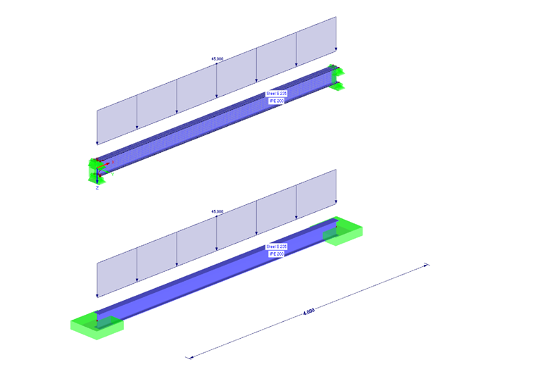
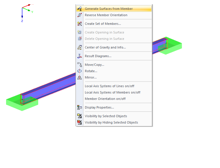
Creating a shell model is very easy in RFEM. There is the option to generate a member element directly into surfaces ("Generate Surfaces from Member" function). A member with a length of 4 m is initially created. The cross‑section type IPE 200 is selected. After modeling the beams, surfaces are generated from the member using the function mentioned above.
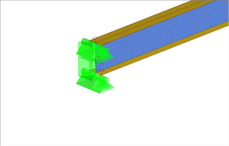
After creating a pure shell model of the beam, you can define the boundary conditions. The beam should be supported on both sides. These boundary conditions can be created with the use of line supports. For this application, the web and flanges of the surface model can be supported with line supports. Complete restraint of the support is not required, as the restraint results from the limit of translational degrees of freedom on the web and the flange.
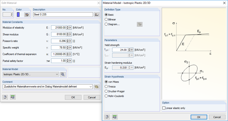
After entering the boundary conditions, you can define plastic behavior of the surfaces by selecting the Isotropic Plastic 2D/3D material model. This material model allows you to consider the surface plastification during the calculation. You can also set the von Mises equivalent stress in the same dialog box, as the material’s yield strength is set to 24 kN/cm². When you specify the plastic behavior of the material, the load increment is automatically activated in the calculation parameters. The load increment will contribute to more efficient convergence behavior in the calculation.
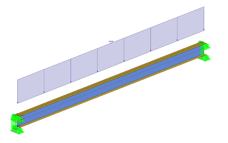
A line load is applied to the structure at the intersection line between the upper flange and the web. The load magnitude is set to 45 kN/m, as plastic hinges begin to form at both support areas for this loading.
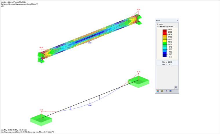
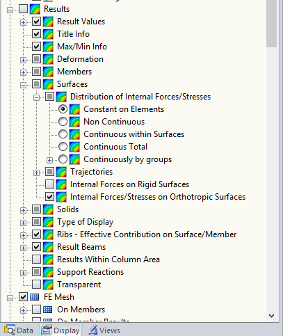
The deformations are available immediately after the calculation of the entire structure. It is possible to switch views to the equivalent stress according to von Mises. The default setting for RFEM displays the stresses with smoothed contours. This causes a distorted view of the results, because the plastic maximum stress is exceeded. Therefore, it is necessary to select the "Constant on Elements" display option for the internal forces and stresses on the surface. These results represent the mean value of each FE element. The node values of the FE element are used to generate the mean value. When using plastic or nonlinear material behavior, it is always necessary to select the "Constant in Elements" display option because the material behavior causes the element values to be plastified, and thus the plastic stress is subsequently displayed correctly.
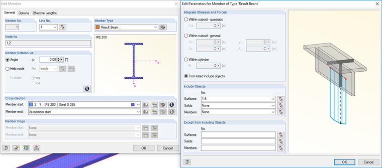
In order to perform a comparison with the analytical calculation, it is necessary to make the results of the surface model comparable to those of the analytical model. For this, it is possible to use a result beam. With a result beam, all surface or solid stresses in the model can be integrated together. A comparison with the analytical model can further be performed.
Defining the member in this model is very easy. When the 1D member is generated into a surface model, a dummy member appears in the location of the original member, which serves as a placeholder. This member has no stiffness and will not be considered in the calculation. You can change the member type from "Dummy" to "Result Beam", and all surfaces can then be assigned to this result beam to view the internal forces as one resultant value. For this example, the flange and web surfaces are included in the result beam to view the elements’ internal force results as if it were a single member.
Entering a Member Model
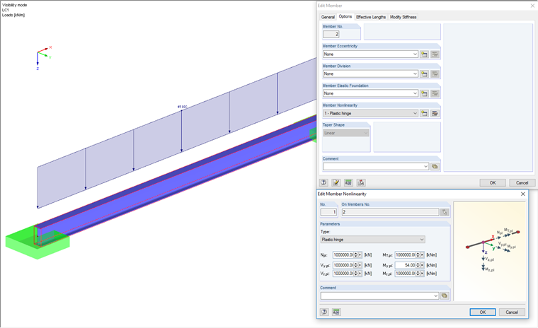
For comparison, a simple member model is now created and loaded to form a plastic hinge. A simple member with an IPE 200 cross‑section is defined. For this member, we will create an added material with isotropic material properties. Steel type S235 is selected for this entry. There is the additional option to consider a plastic hinge under Member Nonlinearity. Since only a plastic moment release should be defined, all the other internal forces are set to a large value so they remain unaffected. The plastic limit moment for IPE 200 with S235 can be calculated by the following:
Mply = fy ∙ Wply
Mply = 24 kN/cm2 ∙ 220.6 cm3 = 54 kNm
The boundary conditions are assumed to be restrained on both sides in order to compare the current model to the previous surface model. The load is applied as a member load in this example due to the fact that line loads can be used for surfaces only. The maximum member load is 45 kN/m.
Evaluation of Comparative Calculation
The results of both calculations can now be compared in the graphic below. The results are almost identical. With the surface model, you can clearly see the plastic hinges that have formed on the supports. The resulting internal forces on the result beam are very similar to the internal forces of the member model that includes plastic hinges. The result differences can be attributed to the modeling of the surface model and the idealization of the member model.