


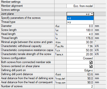
Due to the determination of the forces in the screws, the design is only possible in the main plane of the screw pair. Forces in the other plane of the screw are not considered by the module. Thus, if there are internal forces Vy and Vz, only the selected plane (usually Vz) is considered. However, you can select the joint plane in the module (Image 02).
In our example, biaxial bending is defined to show this way of the design. In a spatial system, forces in the y- and z‑directions will inevitably occur. If these forces become too large, it is possible to perform the interaction with
as a conservative estimation.Structural System
- Main beam = 14/26 GL24c
- Connected beam = 10/16 C24
- Span of the main beam = 5 m
- Span of the connected beam = 3 m
- Load z = 2.2 kN/m (self‑weight by default)
- Load y = 1.0 kN/m
- Connecting shear force Vz = 3.38 kN
- Connecting shear force Vy = 1.13 kN
- Screw-in angle of screws to each other = 45 °
- LDC permanent
Design of Screws
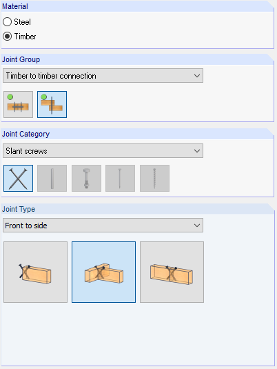
In the add-on module, Joint Type 2 is selected for the main-connected beam joint. Subsequently, connection nodes are selected and loads are defined. General information about the input can be found in the manual for the module. In the Geometry window, the joint plane x-z is selected for the definition of the first design.
The load-bearing capacity of the screw is defined manually according to [1].
For further information regarding the geometry, see the manual.
Design
The design of forces in the screws is shown in the following. In the program, this is done under the internal design numbers 4103 and 4104.
Force by screw in x-z plane:

Design:
Utilization = 65%.
Force by screw in x-y plane:
In the following text, the screw pair is located and designed in the plane rotated about 90° due to double bending.
Design of the x-y plane:
The diameter is changed to 6 mm and the screw length to 140 mm. Therefore, a slightly different load-bearing capacity results. The determination of the load-bearing capacity is not described again.
Utilization = 31%.
Interaction:
Summary
Manual superposition allows for considering double bending in two cases with RF-/JOINTS Timber – Timber to Timber. The tensile resistance and pull-out strength are only considered in the respective plane.