


Theoretical Background for Distance Calculation
To find the FE nodes that are close to or on the line, it is necessary to calculate the distance of the node to the line. The line with the start and end points (N0 and N1), and the point P of which the distance to the line is to be determined, are given. A common way to calculate this distance is to span a plane that runs through point P and is perpendicular to the straight line. For this purpose, a suitable straight line equation has to be set up first. In this case, we recommend using the parameter form, which contains a direction vector v. You can use it to set up the plane equation.
For the support vector A, the starting point (location vector) of the line is used, and for the direction vector v, the difference of the two location vectors is used. The normal form is used as the plane equation for the reason mentioned above.
The support vector P is the result point Pres to be analyzed. The normal vector is the direction vector of the straight line because the plane is orthogonal to the straight line. Before the distance can be calculated, it is necessary to determine the factor s of the line where the plane intersects the line. For this purpose, the location vector X in the plane equation is replaced by the straight line equation.
Rearranged for s and calculated by
the following equation results.Thus, it is possible to determine the intersection point S using Equation 1.
The distance d between S and Pres is determined by means of the vectorial amount of the difference between the two.
Image 01 shows the schematic representation of all listed elements. The blue surface is the surface to be analyzed and the red surface represents the section plane that was set up with point Pres and the direction vector
. The factor s is just 0.5 in the image, so the intersection of plane and line is exactly in the center of the line.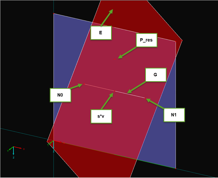
Implementing Distance Calculation in Program
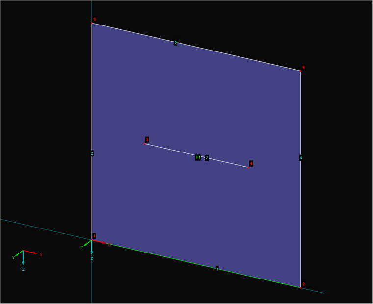
Once the formulas are available, you can create the corresponding program. EXCEL VBA is used for the conversion. Image 02 shows the numbering of the elements.
First, a connection to RFEM is necessary. Then, get the interface for the model data. Since this procedure has already been described in various other articles (see Links), it will not be described in detail here. Below is the source code for starting the program.
Sub selection_test2()

    Dim line_no As Integer
    Dim surface_no As Integer
    Dim loadcase_no As Integer
    Dim d_tol As Double
    line_no = 11
    surface_no = 1
    loadcase_no = 1
    d_tol = 0.001

    '   get interface from the opened model and lock the licence/program
    Dim iModel As RFEM5.IModel2
    Set iModel = GetObject(, "RFEM5.Model")
    iModel.GetApplication.LockLicense

On Error GoTo e

    Dim iModelData As RFEM5.IModelData2
    Set iModelData = iModel.GetModelData
Before starting the program, define the variable parameters. These include the line number (line_no) of the line where you want to search for results, and of course, the surface number (surface_no) of the surface where the line is located. Furthermore, you need the number of the load case (loadcase_no) to which the results belong. Since this is a numerical calculation with limited accuracy, a tolerance (d_tol) is required, which specifies the maximum distance between line and node. In this example, a tolerance of one millimeter is used.
Since the interface for the model data (IModelData) is now available, you can search for the line first and, thus, also its start and end points.
   '   get line
    Dim ILin As RFEM5.ILine
    Set ILin = iModelData.GetLine(line_no, AtNo)
    Dim lin As RFEM5.RfLine
    lin = ILin.GetData


    '   get nodes from line
    Dim n(0 To 1) As RFEM5.Node

    Dim ints() As Integer
    ints = strToIntArr(lin.NodeList)

    Dim iNd As RFEM5.INode
    Set iNd = iModelData.GetNode(ints(0), AtNo)
    n(0) = iNd.GetData
    Set iNd = iModelData.GetNode(ints(UBound(ints, 1)), AtNo)
    n(1) = iNd.GetData

    Set iNd = Nothing
You get both the nodes and the line individually, directly via their interface (INode or ILine). To extract the node numbers from the string (RfLine.NodeList), use the strToIntArr function described in another article (see Links). It converts the string into an integer field.
With the points now given of the line
(start point) and (end point), you can set up the first parameters of the equation. Dim v As RFEM5.Point3D
v.X = N(1).X - N(0).X
v.Y = N(1).Y - N(0).Y
v.Z = N(1).Z - N(0).Z
Dim A As RFEM5.Point3D
A.X = N(0).X
A.Y = N(0).Y
A.Z = N(0).Z
Dim v2 As Double
v2 = v.X ^ 2 + v.Y ^ 2 + v.Z ^ 2
Dim P_res As RFEM5.Point3D
Dim s As Double
Dim d As DoubleThe direction vector
(v), the support vector (A), and the scale product of the direction vector (v2) are calculated or prepared. Furthermore, the variables Pres (P_res) for the point of the result and s for the factor from the linear Equation (1) are also defined.Calculating Distance in Loop
In this example, processing the results on the basis of the FE nodes has been selected. The check of the distance takes place in a loop over the field of these results. First, you have to get these results via the ICalculation2 interface, then IResults. Within the loop, the point Pres is first described with the coordinates of the result value (for clarity). Then, you can perform the direct calculation of Equation (4). After s has been calculated, it is possible to check if the value is less than zero or greater than one, because these values lie outside or before and after the straight line. If a value is within this range, the distance is calculated with Equation (6).
    '       get results in fe-nodes
    Dim iCalc As ICalculation2
    Set iCalc = iModel.GetCalculation

    Dim iRes As RFEM5.IResults
    Set iRes = iCalc.GetResultsInFeNodes(LoadCaseType, loadcase_no)

    Dim surfBaStr() As RFEM5.SurfaceBasicStresses
    surfBaStr = iRes.GetSurfaceBasicStresses(surface_no, AtNo)

    '       loop through stresses and calculate distance to line
    Dim i As Integer
    For i = 0 To UBound(surfBaStr, 1)
        P_res.X = surfBaStr(i).Coordinates.X
        P_res.Y = surfBaStr(i).Coordinates.Y
        P_res.Z = surfBaStr(i).Coordinates.Z
        '   calculate factor for line equation of intersection
        s = ((P_res.X-A.X)*v.X + (P_res.Y-A.Y)*v.Y + (P_res.Z-A.Z)*v.Z) / v2

        If s <= 1 + d_tol And s >= 0 - d_tol Then
            '   calculate distance of intersection point and fe-node
            d = ((P_res.X-(A.X+s*v.X))^2
                 +(P_res.Y-(A.Y+s*v.Y))^2
                 +(P_res.Z-(A.Z+s*v.Z))^2)^0.5

            If (d < d_tol) Then
                ' here you can process the found result point
            End If
        End If

    Next i
The tolerance is applied to both the check of the factor s and the distance d, so that any minor inaccuracies do not lead to the exclusion of a result.
Results of Program
The values found by the program are shown in the table, with the values rounded to two decimal places.
| σy+ [N/mm²] | Factor s [-] |
|---|---|
| 21.90 | 0.0 |
| 17.28 | 0.1 |
| 12.79 | 0.2 |
| 8.43 | 0.3 |
| 4.17 | 0.4 |
| -0.04 | 0.5 |
| -4.25 | 0.6 |
| -8.51 | 0.7 |
| -12.87 | 0.8 |
| -17.36 | 0.9 |
| -21.98 | 1.0 |
As a comparison, the values from the result diagram on the corresponding line are displayed in Image 03.
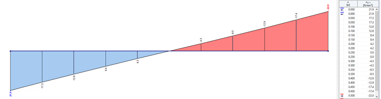
It is clearly evident that the values are the same and there is a 100% match, or that all the values were found on the line.
Conclusion
With the help of vector calculation, a program has been created that is able to find nodes along a line. With this algorithm, it is also possible to search not only results, but all other geometric elements. This is especially helpful because the visual selection is, of course, impossible via the COM interface, but is thus possible via a function in another way. It is possible to perform an automatic result evaluation in particular for programs that run completely in the background.
