


Origin
Cranes have been used on construction sites for more than 2,500 years. Over time, cranes have been developed further. In order to move large loads without motors, both lever rules and force increases were used by means of several rope lines and sheaves. These simple but ingenious basic principles are still used today.
What is Block and Tackle Pulley System?
A block and tackle pulley system is a mixed structure consisting of a cable and at least one pulley wheel and is used to lift loads. With the use of several pulleys, the force required to lift a certain mass piece can be reduced further. Some of the pulleys have a fixed position, while others are loose pulleys moving during the lifting process. The advantage of increasing the force must be compensated by a longer pulley distance.
Four Typical Pulley Systems
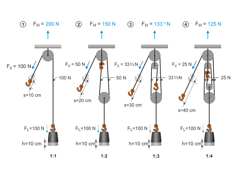
The following text describes four pulley system options with downward tension force. In the model file, which you can download at the end of this article, you will find a structure that is as realistic as possible, including a simple schematic modeling for better understanding the behavior.
This example shows for each type how to lift a weight of G = 100 N over a height of u = 100 mm. where:
| F | Force required to lift the weight, corresponds to the lower left support in the RFEM model |
| n | Number of supporting cable sections |
| Δl | Required pulling distance to increase the weight by u |
For this pulley system type, the required pulley distance is determined by Δl = n · u.
Implementation 1: 1
F = G
Δl = u
Implementation 1: 2
F = 0.5 · G
Δl = 2 · u
Implementation 1: 3
F = 1/3 · G
Δl = 3 · u
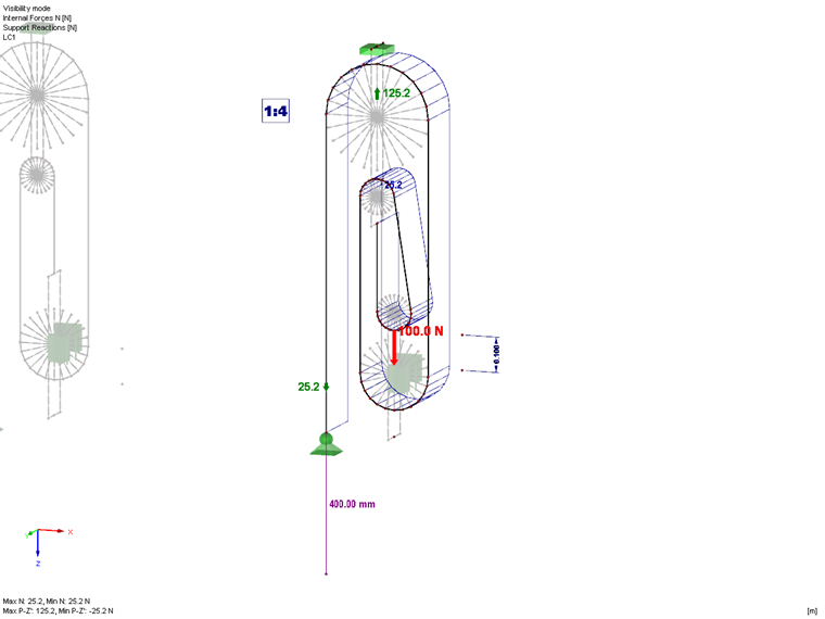
Implementation 1: 4
F = 1/4 · G
Δl = 4 · u
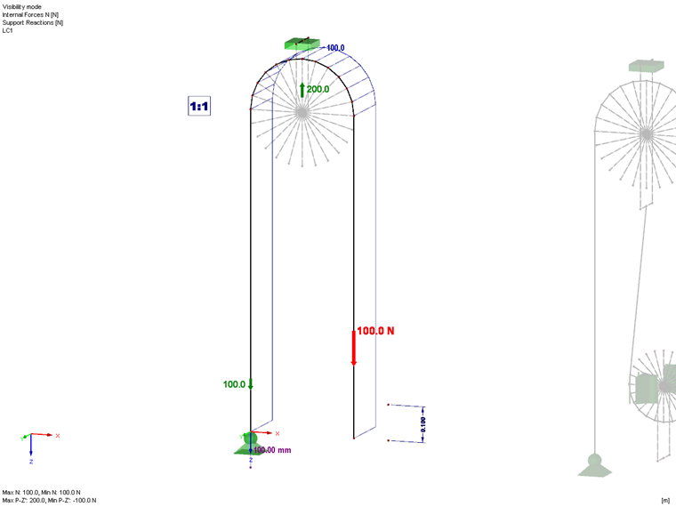
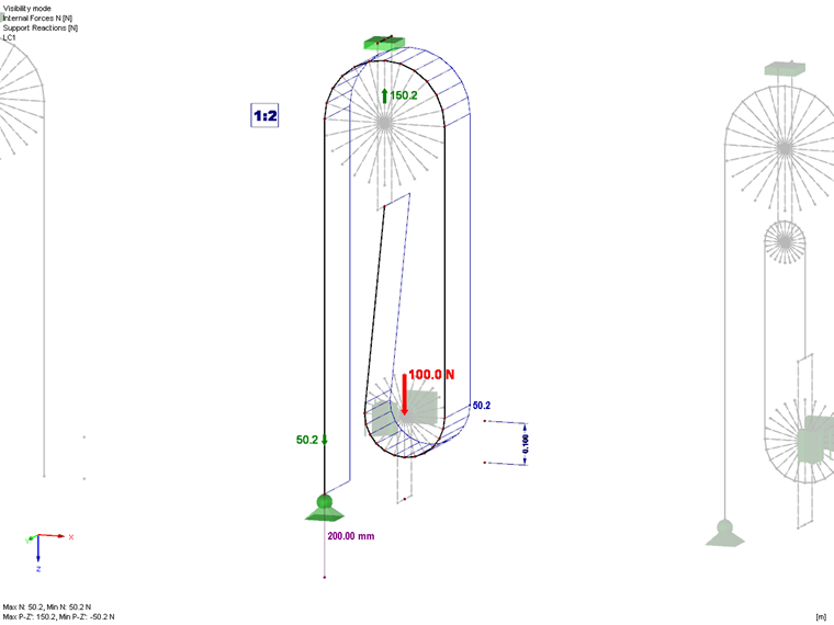
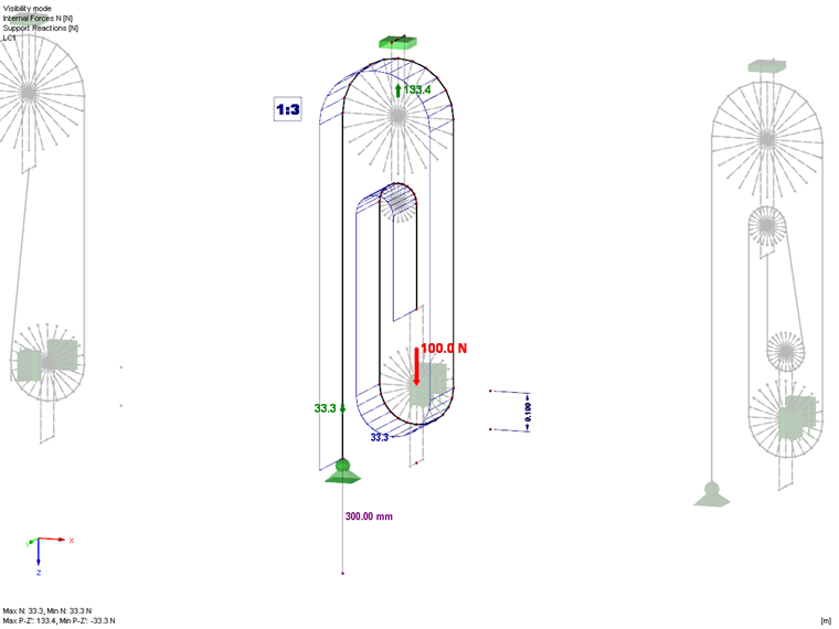
Modeling in RFEM
During the modeling, you have to enter the cable as a continuous polyline with at least three nodes. Thus, the program "knows" it is an element that is an entire cable. Then, you can assign the "Cable on Pulleys" member type to this polyline. At least one end of the cable must have an immovable support or a member so that the applied tensile load can be transferred. Since the tensile force should be constant in a "Cable on Pulleys", the elements connected during the modeling process do not need any further definition. The adjacent elements or nodal supports receive deviation forces if there is buckling on the cables.
When modeling, rigid members were applied in such a way that the slab force can be displayed on a support. Additional stabilizing supports were arranged on the loose pulleys to counteract the instability.
The required pulling distance was applied by means of an imposed nodal deformation.