


Usually, structures are not considered to be susceptible to vibrations if the deformations under wind action by gust resonance are not increased by more than 10 % [2]. In this case, the time-variable wind action can be described as a static equivalent load.
Assuming that the turbulences within the wind flow are very large in relation to the building dimensions, a statically acting distribution of pressure p on a building geometry can be calculated with RWIND Simulation according to the "quasi-stationary method" or the so-called gust concept [3].
Basically, a stationary flow field around the analysis model is assumed for the turbulent speed fluctuation over the gust's duration [3]. The pressure fluctuation on the model surface from the inflow turbulence is thus seen as a state stationary over the certain time period t. Thus, the fluctuations follow exactly the course of the time-averaged pressure coefficients cp,mean on the model surface.
The resulting wind-induced pressure Δp(t) on the model surfaces then depends purely on the inlet velocity v(t).
|
ρ |
Dichte der Luft |
|
v |
Anströmgeschwindigkeit |
|
cp,mean |
Zeitlich gemittelter Druckbeiwert |
|
t |
Zeit |
Thus, the value of the inlet velocity vector v(t) is:
v(t)² = (vx,mean + vx,fluctuation(t))² + vy,fluctuation(t)² + vz,fluctuation(t)²
If the squared terms only make a small contribution, the effective value of the inlet velocity vector v(t) is the result:
v(t)² = vx,mean² + 2 ⋅ vx,mean ⋅ vx,fluctuation(t)
Using the effective inlet velocity in the equation of the wind-induced pressure results in:
Δp(t) = 1/2 ⋅ ρ ⋅ vx,mean² [1 + (2 ⋅ vx,fluctuation(t)) / vx,mean] ⋅ cp,mean
This transformation shows that the fluctuation of the wind pressure Δp(t) only depends on the fluctuation of the wind speed vx,fluctuation(t) in the main inflow direction x.
If you replace the time-variable speed fluctuation vx,fluctuation(t) by the maximum occurring speed fluctuation vx,fluctuation,max, you remove the temporal variability from the system.
If you then compare the term vx,fluctuation,max / vx,mean as a multiple g of the turbulence intensity Iv(z),
|
δv |
Standardabweichung zur mittleren Geschwindigkeit vmean |
|
vmean(z) |
Mittlere Geschwindigkeit abhängig von der Höhe |
|
z |
Höhe über Grund |
you can describe the term in square brackets as the gust factor G(z). Inserting the terms into the nominal wind load equation results in:
|
ρ |
Dichte der Luft |
|
vmean |
Mittlere Anströmgeschwindigkeit |
|
G(z) |
Böenfaktor abhängig von der Höhe |
|
cp,mean |
Zeitlich gemittelter Druckbeiwert |
where
|
g |
Faktor zur Festlegung der Böendauer |
|
Iv(z) |
Turbulenzintensität abhängig von der Höhe |
|
z |
Höhe über Grund |
For example, in EN 1991‑1‑4, factor g is used for describing the gust duration 3.5.
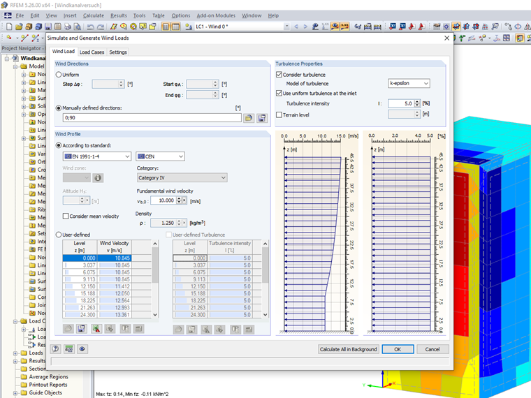
RWIND Simulation calculates the mean values of the pressures pmean on the model surface depending on an inlet velocity vx(z) by means of a stationary solution of the RANS equations using the SIMPLEC algorithm. Since the mean values of the pressure coefficients cp,mean are based on the ratio between the determined mean pressure values pmean to the undisturbed peak wind velocity pressure at the roof height q(height of roof),
cp,mean = pmean / q(height of roof)
it is possible to use the inlet velocity from the converted peak wind velocity pressure q(z) over the height to determine the nominal wind loads according to the gust concept [1].
v(z) = √(2 ⋅ q(z) / ρ)
Thus, this wind speed includes the mean wind velocity vmean and the maximum fluctuation component vfluctuation. In this case, the inflow turbulence intensity can be set constantly over the height to a very small value of about 5 % [4].
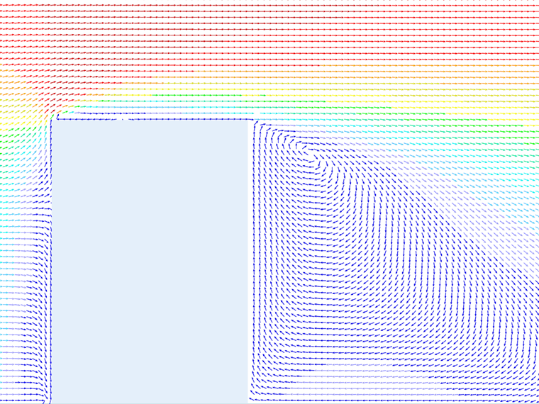
When considering effects of forces acting on the entire building or on large surface areas, this method provides a very good approximation to the natural wind loading [3]. The reason is that the small turbulence effects masked by averaging act only in partial areas and do not have a noticeable effect due to the global integration of the force values.
Furthermore, the concept reacts very well even for small partial areas with frontal inflow since here the effective pressure fluctuations are already very well recorded in the peak wind speed profile [3].
Conversely, the system results in poorer convergence with the reality for surfaces with flow separation (side and rear walls). It is especially in these zones that the building-induced turbulence "faded away" by averaging using the gust concept has a greater effect than the inflow turbulence effect contained in the inlet velocity profile.
