


Effective Lengths in RFEM 6
In order for the stability design checks to be included in the Steel Design results, it is important to assign effective lengths to the members before performing the design. In RFEM 6, the effective length is not a local setting of one member only. Hence, each effective length that has been defined in the program can be assigned to several members or sets of members at the same time.
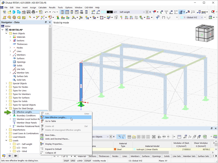
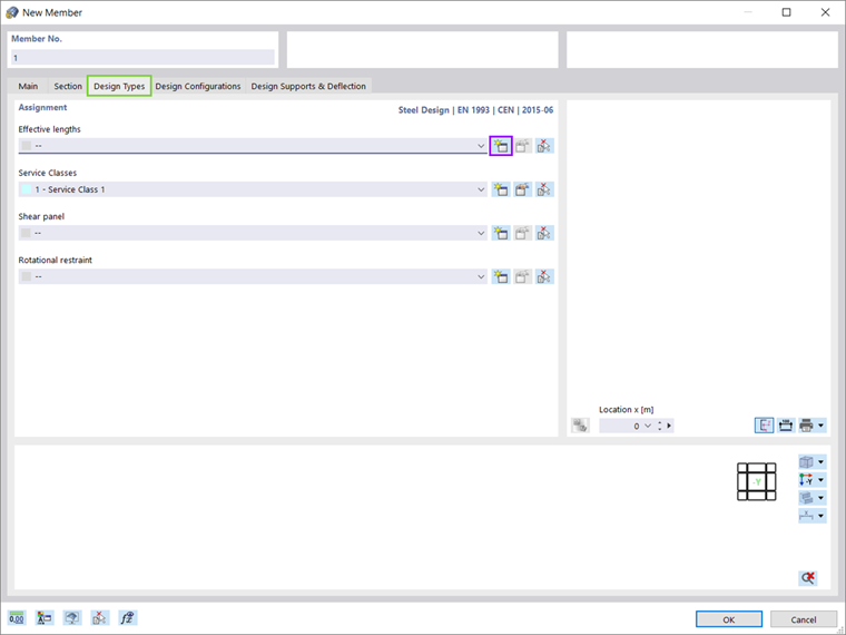
Assuming that the Steel Design add-on is activated in the Base Data of the model, new effective lengths can be defined via the Data tab of the navigator (Image 1). Alternatively, it is possible to define effective lengths via the Design Types tab of the member window (Image 2).
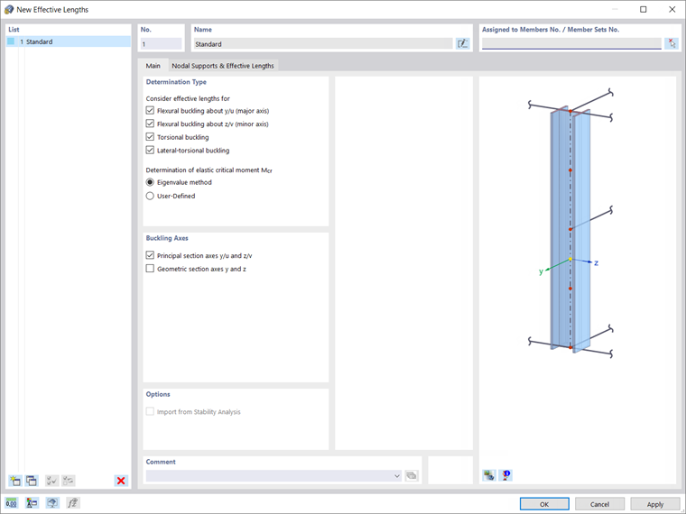
Regardless of the approach by which it is determined, the effective length can be considered for flexural buckling around the major and minor axes as well as for torsional and lateral-torsional buckling (Image 3).
1. Defining Effective Length via Nodal Supports and Effective Length Factors
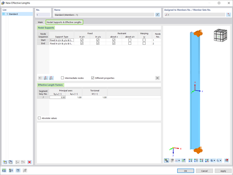
First, we will demonstrate how to define the effective length based on the consideration of the nodal supports and effective length factors with respect to the support conditions of the member (Image 4).
Given the support conditions of Column 1, nodal supports of the support type fixed in both principal directions z/v and y/u as well as torsion (restraint around x) should be defined only at the start and end of this member. Since there are no intermediate supports dividing the member into segments of different lengths, the effective length factors should be calculated manually and adjusted for the whole member length as a single segment.
In this example, the column of interest is connected to a horizontal beam as a frame and therefore, the expected buckling length for the principal axis y is approximated at 3.5, whereas the effective length factor for out-of-plane buckling is 1.
2. Importing Effective Length from Stability Analysis
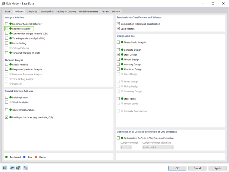
However, RFEM 6 offers another option to define the effective lengths of members: by importing them directly from the stability analysis. For this purpose, it is necessary to activate the Structure Stability add-on (Image 5).
In this approach, the stability analysis should be performed to obtain the relevant mode shapes and the associated effective lengths of separate members. Later, the effective lengths can be assigned to the members of interest and can be considered for the steel design.
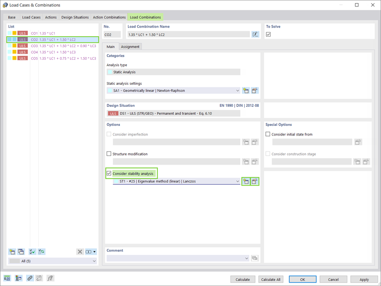
In RFEM 6, the consideration of the stability analysis is done in terms of separate load cases and combinations, as shown in Image 6. In this example, the stability analysis will be considered for Load Combination 2 (self-weight and snow) due to the compression associated with it.
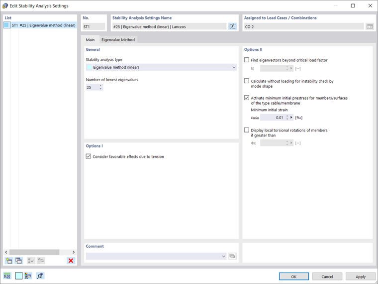
The stability analysis settings can be defined easily in the window shown in Image 7. For instance, the stability analysis type (eigenvalue method, incremental method with eigenvalue analysis, incremental method without eigenvalue analysis), the number of lowest eigenvalues, and the possibility to consider favorable effects due to tension should be adjusted if one of the eigenvalue methods is preferred (Lanczos, roots of characteristic polynomial, subspace iteration or ICG iteration).
In a similar way, the parameters for the incrementally increasing loading should be defined when an incremental method is favored.
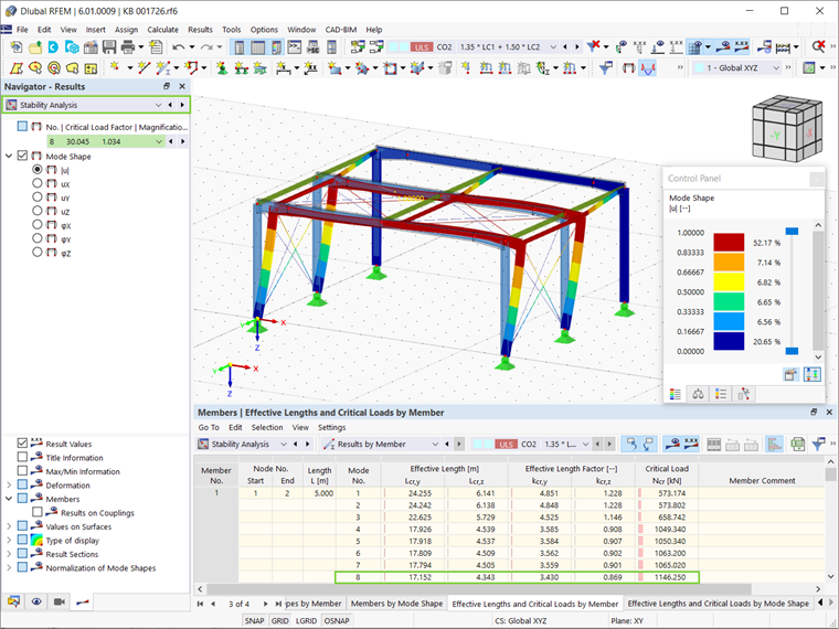
Once the calculation is run, the results are displayed both graphically and in the Stability Analysis Results table. The buckling length for which the column buckles in the frame plane is the correct length for the design of the respective load situation. In this example, the eigen form that represents buckling in the global X direction is Mode Shape 8 (Image 8).
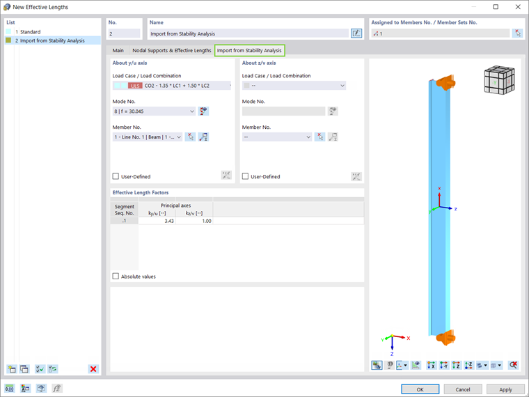
As a matter of fact, it is now possible to import the effective length from the stability analysis. When the option is selected in the Effective Length window (Image 9), the load case/combination, the eigen mode, and the member from which the effective length should be imported can be defined in an associated tab. Since the effective length will be assigned to Column 1, these are Load Combination 2, Mode 8, and Member 1, respectively (Image 10).
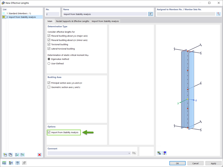
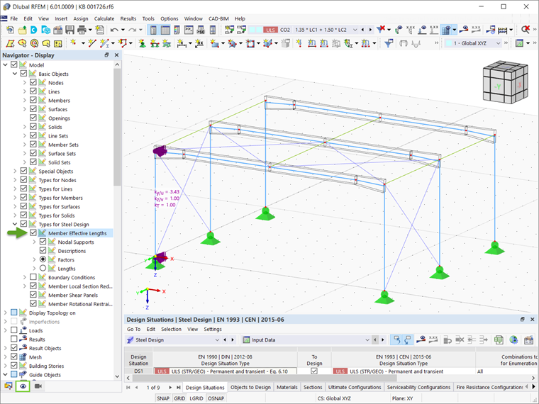
In RFEM 6, it is also possible to display the assigned length graphically, as shown in Image 11.
By defining the effective length settings, a balancing act is performed between the buckling lengths and the flexural torsional buckling property settings. With the support checks, the element is divided into segments for the buckling processes. At the same time, the support checks serve to describe the boundary conditions for the eigenvalue-related calculation of the critical lateral torsional buckling moment (Mcr).
Stability Checks in Terms of Steel Design
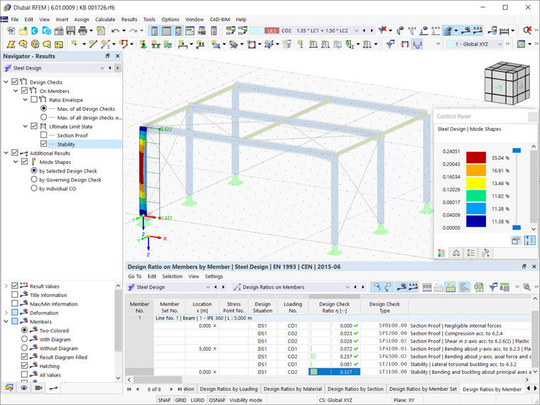
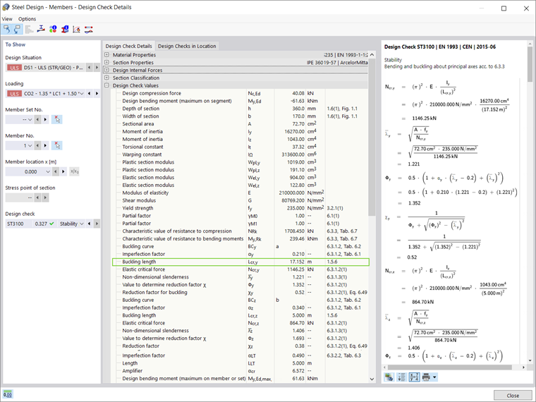
Once the effective length has been assigned to the member of interest, the Steel Design can be calculated. As Image 12 shows, the stability checks are among the results displayed in the Results table. The buckling length is included in the Design Check Details (Image 13). As expected, the stability check is performed on the basis of the effective length calculated by the stability analysis.
Final Remarks
The effective length for the equivalent member design in RFEM 6 can be determined manually, or it can be imported from a stability analysis. In the first approach, the effective length is determined by assigning nodal supports and adjusting the effective length factors manually with respect to the support conditions of the member.
In the second approach, on the other hand, the effective length is an output of the stability analysis, and thus can be assigned directly to the member for design purposes. The advantage of this approach is that the effective length factors and the effective length itself are calculated automatically. This is very convenient for certain support conditions that would otherwise have required exhausting manual calculation.
However, it is important to consider the correct effective length in terms of buckling mode and respective load situation when importing it from the stability analysis.