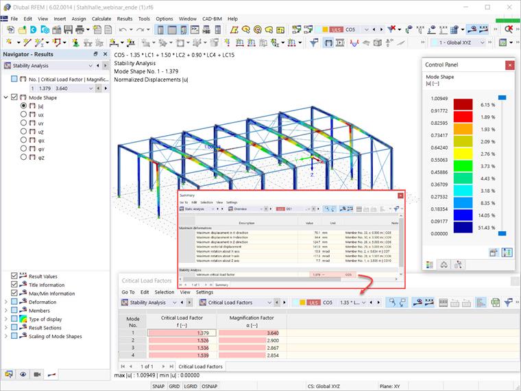
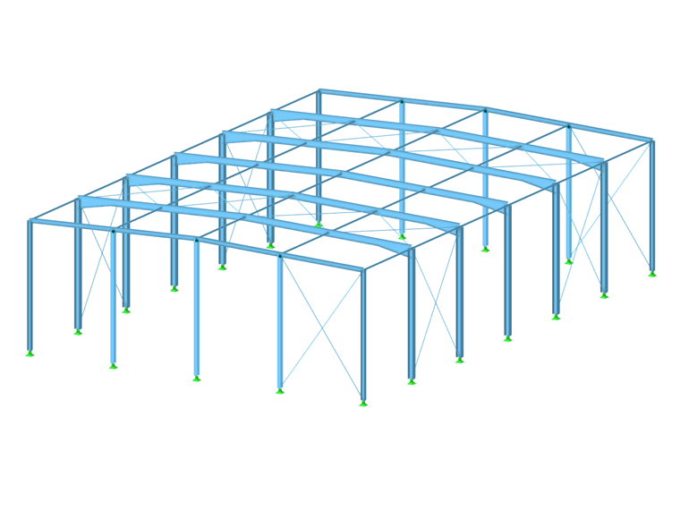
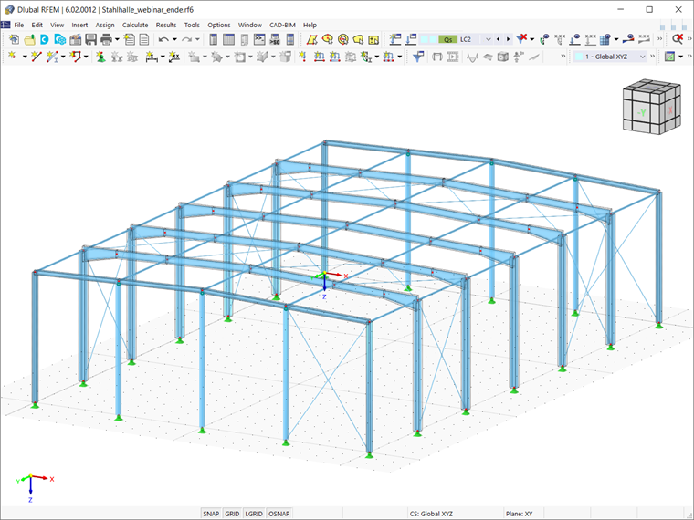
This article will show you a practical example of how to carry out a lateral-torsional buckling analysis for the steel hall shown in Image 1. You also can see this article as a continuation of the article titled
Determination of Critical Load Factors Using Structure Stability Add-on in RFEM 6 and RSTAB 9
, which shows how to use the Structure Stability add-on to determine critical load factors and the corresponding stability modes for this 3D model.
Nevertheless, the aforementioned article observed that consideration of torsional warping in the stability analysis of the structure is necessary due to the results of the static analysis (that is, applied loads result in bending moments My, so a lateral torsion buckling problem of the main beam is expected as well).
As a result, the following text will show you how to use the Torsion Warping (7 DOF) add-on in combination with the Structure Stability add-on to consider cross-section warping as an additional degree of freedom when performing the stability analysis. It is important to know that the calculation is on the entire model, so the stiffness of the adjacent members or defined support conditions is considered automatically.
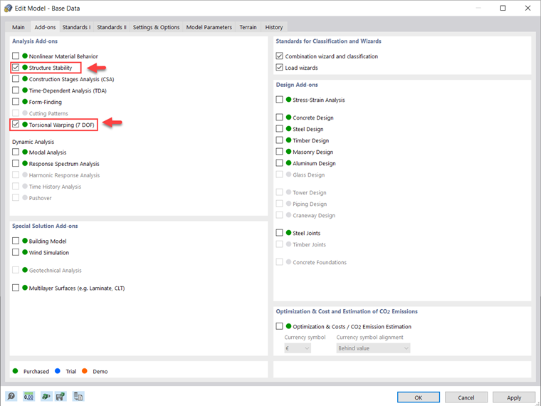
Both the Torsional Warping and Structure Stability add-ons can be found in the Base Data, as shown in Image 2. You must know that in RFEM 6 and the Torsional Warping add-on, warping is associated with members only; therefore, no global support conditions have to be defined for it.
Furthermore, the warping at the member ends is assumed to be unobstructed by default; hence, you should use Member Transverse Stiffeners to define warp springs at the member ends and consider the warping stiffness or warping stress. You can read more about this in the Knowledge Base article
Lateral-Torsional Buckling Design with New Torsional Warping (7 DOF) Add-on for RFEM 6 / RSTAB 9
.
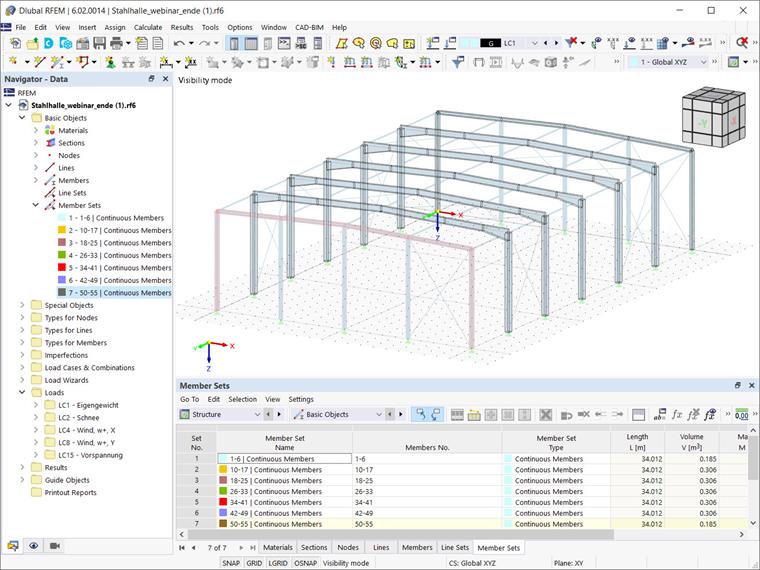
Since the warping is assumed to be unhindered at the member end, there is no transfer of the momentum between adjacent members. In other words, all members are considered individually for the warping calculation (that is, individual members can warp freely at their ends). To transfer the warping between individual members that are connected, you can define a set of members. In this regard, the main beams of the steel hall of interest are defined as separate sets of members, as shown in Image 3.
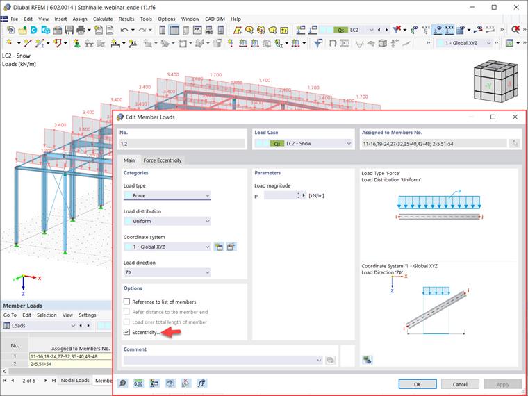
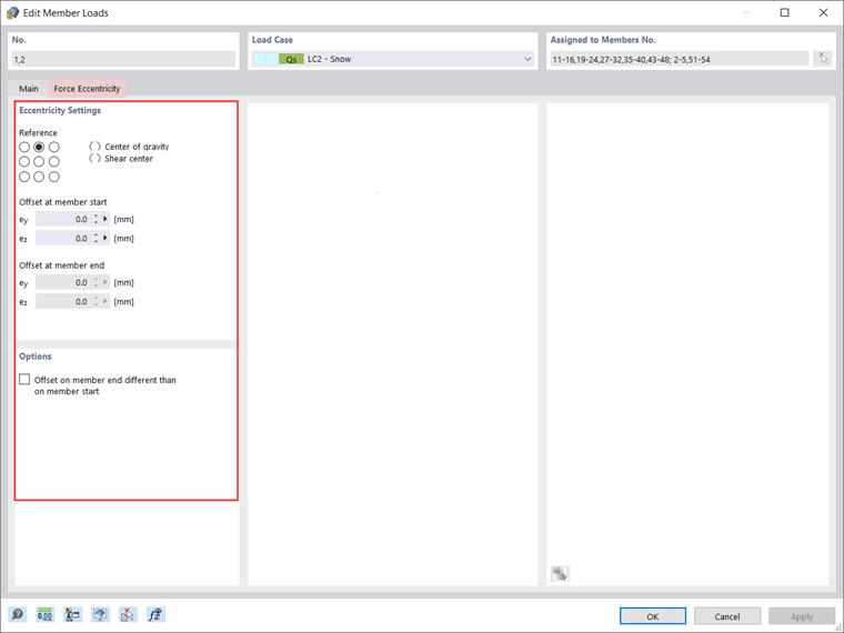
At this point, a parallel can be made between the load application point when calculating members with 6 degrees of freedom, and calculating members with 7 degrees of freedom. Namely, if other objects are connected to a member to be calculated with 6 degrees of freedom, shear forces from other components are introduced at the shear center.
When calculating members with 7 degrees of freedom, however, the connection point is considered to be in the center of gravity (that is, the centroid of the cross-section), and the defined member loads are also applied there. To address this issue in the analysis, you can define member eccentricities or use rigid members to define such connections. In this regard, the application point of the load in this example will be defined with the eccentricity shown in Images 4 and 5.
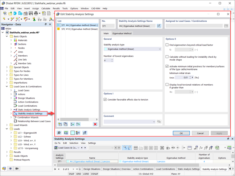
Next, the stability analysis settings can be defined in the same way as explained in the Knowledge Base article
Determination of Critical Load Factors Using Structure Stability Add-on in RFEM 6 and RSTAB 9
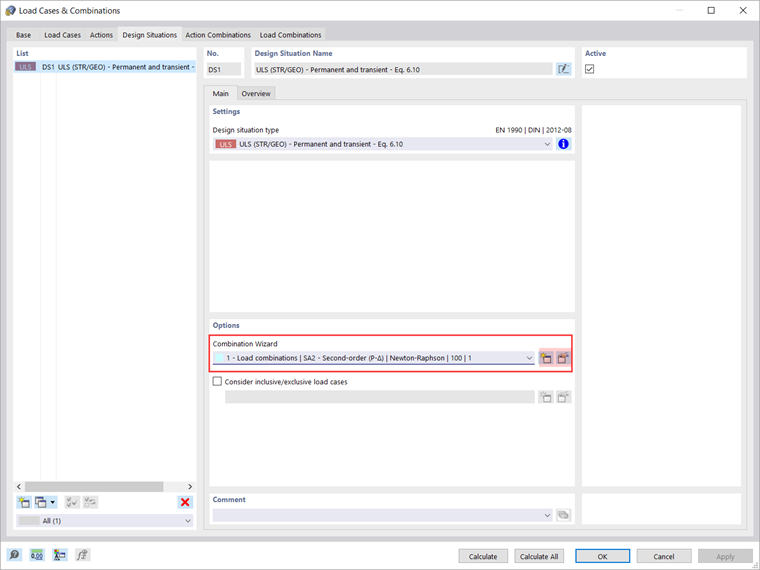
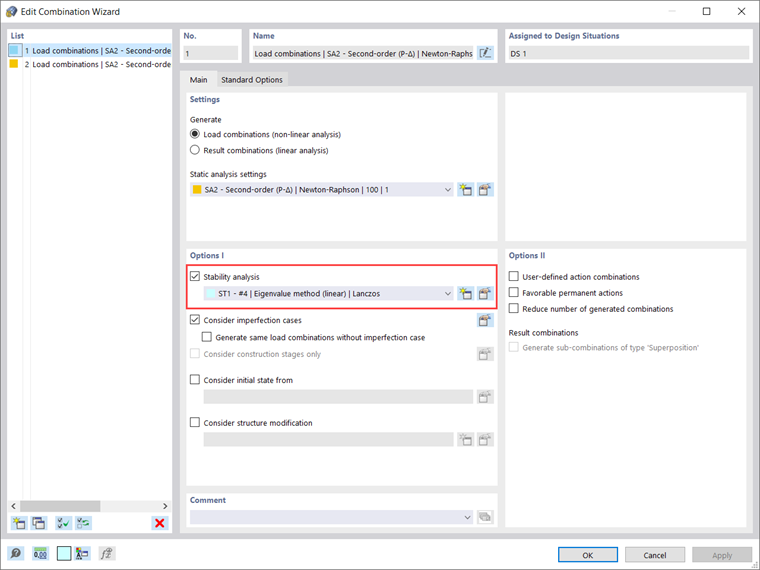
. Namely, you can select the analysis method and consider the other options shown in Image 6.
As discussed in the aforementioned article, the stability analysis can be considered in terms of load cases, load combinations, and design situations. In this example, the stability analysis is considered in terms of the ultimate design situation, as shown in Images 7 and 8. Hence, you can calculate this design situation and obtain results in the same way as discussed in the aforementioned article.
Finally, you can run the calculation and obtain the results of the stability analysis with consideration of the cross-section torsional warping. In the Overview of the Static Analysis table, you can see the most critical load factor of all the load combinations (Image 9), together with the governing load combination with which the critical load factor is associated. This way, you can open the stability analysis results for the specific load combination and display the associated mode shape.