The Finite Element Method (FEM) is a numerical method for solving complex mathematical tasks by discretizing the domain of the problem into small parts called finite elements. RFEM 6 is a structural analysis software that employs the FEM to meet all requirements in modern civil engineering.
Since internal forces, deformations, and stresses are results of the FEM calculation, they are determined as nodal values for the FE mesh nodes. For a continuous distribution of these results, the nodal values can be smoothed, as will be explained in this article.
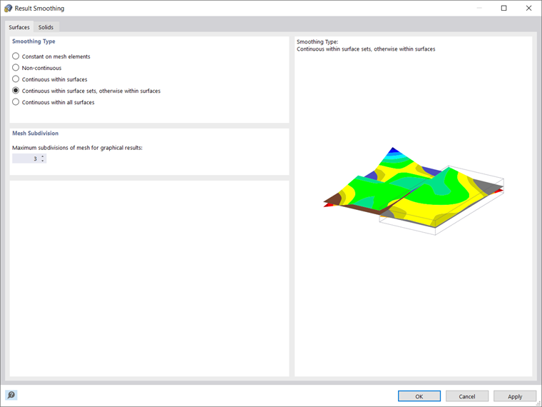
You can find the settings for result smoothing in the associated dialog box, accessible via the “Calculate” menu. As you can see in Image 01, this dialog box has two tabs: Surfaces and Solids. The former controls whether and how surface results are interpolated, whereas the latter controls the same for the boundary surfaces of solids.
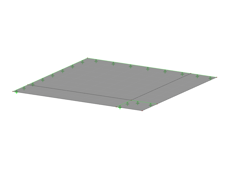
The available smoothing types are the same for surfaces and solids and are presented in more detail down below. To better illustrate how smoothing works, each type of smoothing is applied to the same model (see Image 02), which consists of four surfaces with identical loads.
Constant on Mesh Elements
The first option at your disposal is to display a constant distribution of the results on mesh elements by averaging the result values on the grid nodes. Hence, there is no distribution in the FE element as with the other options, and the entire FE element has the same “smoothed” value (see Image 03).
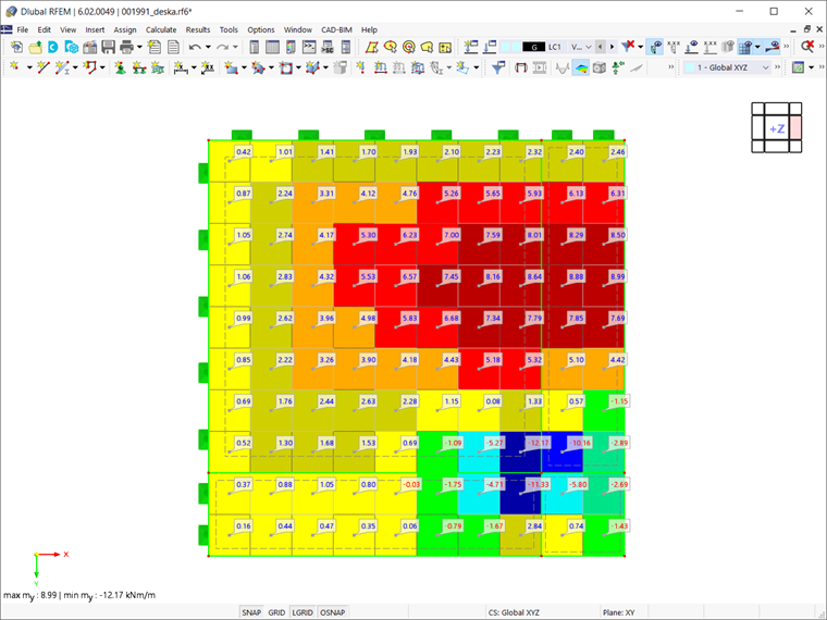
This is the type of result smoothing to be employed when using nonlinear material models, due to the iterative calculation that the program performs when working with these material models. Based on the model chosen, a different relationship is defined between the stresses and strains, and the stiffness of the finite elements is continually adjusted throughout the iterations until the stress-strain relationship is satisfied. Given that the adjustment is always made for an entire surface or solid element, it is recommended to use this particular smoothing type.
Non-Continuous
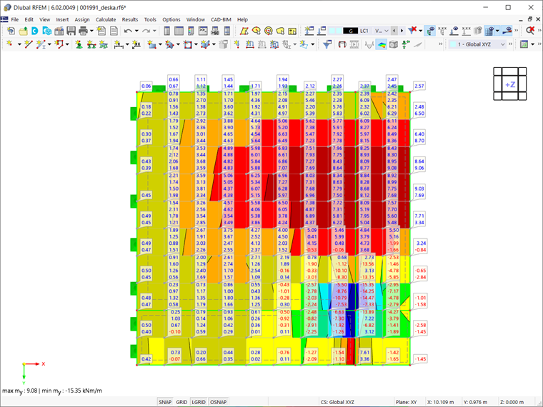
This representation of the results is shown in Image 04. As depicted, the values of the FE nodes of each individual element are presented by selecting the "Non-continuous" smoothing type. Consequently, multiple values are displayed for a single node. The smoothing type is called “Non-continuous” due to the discontinuous distribution resulting from the fact that the FE nodal values are not averaged with neighboring elements. Significant differences between FE elements indicate that a finer mesh is necessary for more accurate calculation results.
Continuous Within Surfaces
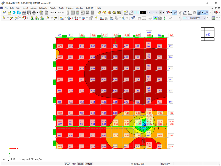
As the name suggests, this type of smoothing shows a continuous distribution of results within a single surface (see Image 05). By selecting this option, the values of all FE elements adjacent to an FE node are averaged and only one value is displayed at each node. However, the averaging ends at the surface boundary and discontinuities between adjacent surfaces can occur as a result. A classic example of this is the results along the support surface of the cantilever, which are discussed at the end of the article.
Continuous Within Surface Sets, Otherwise Within Surfaces
This option can be seen as an extension of the "Continuous Within Surfaces" result smoothing, since the adjacent areas of the surfaces contained in the surface set are also taken into account during the interpolation if there are surface sets in the model. Hence, in contrast to the "Continuous within surfaces" option, this option favors the continuous effect of the surfaces in the support area.
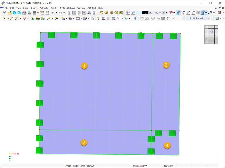
To demonstrate this type of smoothing on the model of interest, surfaces No. 1 and No. 2 are combined into a surface set. As Image 06 shows, because of this type of smoothing, there is a continuous distribution of results within the set (that is, between surfaces No. 1 and No. 2). For surfaces No. 3 and No. 4, however, the distribution is continuous only within their own boundaries.
Continuous Within All Surfaces
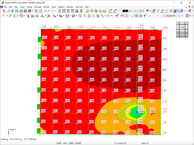
Unlike the “Continuous within surfaces” smoothing type, where averaging ends at the edge of a single surface, this type of smoothing results in a continuous distribution between adjacent surfaces (see Image 07). This means that surfaces do not have to be in a surface set, as was the case with the “Continuous within surface sets, otherwise within surfaces” smoothing type. This is because values are averaged across all surface boundaries by default.
It is, therefore, important that the axis systems of the surfaces are aligned in the same direction when using this type of smoothing. To avoid an incorrect display of the results, it is important to ensure that a maximum of two surfaces lying in one plane border one another and that the boundary line does not have a line hinge.
Summary
As shown in the images for the different smoothing types, each type can lead to a different distribution of results. The "Continuous within surface sets, otherwise within surfaces" option is the default, as it gives the best results in most cases. However, each case you work on should be evaluated individually, and you should choose the smoothing option that provides the best results.
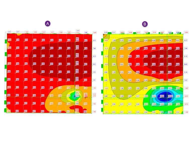
For example, if you compare the results for the "Continuous within surfaces" option (A) and "Continuous within all surfaces" (B) (see Image 08), you might be confused as to why the former shows different negative moments at the support location. Now that you are familiar with the different types of smoothing, you know that this is due to the smoothing type you set in the Result Smoothing dialog box.