12 Results
View Results:
Sort by:
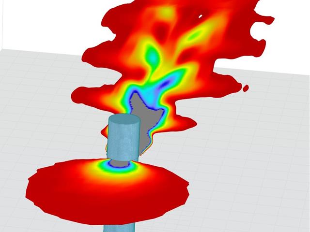
Modeling a Kármán vortex street in RWIND

In RFEM 6 it is possible to save selected objects (as well as whole structures) as blocks and reuse them in other models. Three types of blocks can be distinguished: non-parameterized, parameterized, and dynamic blocks (via JavaScript). This article will focus on the first block type (non-parameterized).
This article describes how to create a user-defined antenna bracket to be used in RF-/TOWER Equipment.
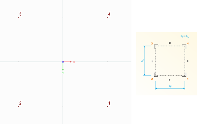
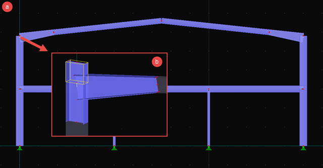
The following technical article describes the creation of a user-defined platform for use on a four-sided tower in the RF-/TOWER add-on modules. First, start with an empty model of the 3D type and define four nodes. The numbering and position of these nodes are very important here.
Numerous nonlinearities can occur in a structural system. The RF-DYNAM Pro - Nonlinear Time History add-on module was developed in order to model them realistically in a dynamic analysis. To explain how the add-on module works, the procedure is described below with an example.
- 001545
- Modeling | Structure
- RFEM 5
-
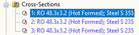
- RF-FRAME-JOINT Pro 5
- RF-JOINTS Timber | Timber to Timber 5
- RF-JOINTS Timber | Steel to Timber 5
- RF-JOINTS Steel | Rigid 5
- RF-JOINTS Steel | DSTV 5
- RF-JOINTS Steel | Pinned 5
- RF-JOINTS Steel | Tower 5
- RF-JOINTS Steel | SIKLA 5
- RF-JOINTS Steel | Column Base 5
- Steel Structures
- Mechanical Engineering
- Cranes and Craneways
- Towers and Masts
- Process Manufacturing Plants
- Steel Connections
- Finite Element Analysis
- Structural Analysis & Design
- Eurocode 3
- DIN 18800
With RF-/FRAME-JOINT Pro, you can design frame joints according to DIN 18800 or Eurocode 3. When dealing with non-standardized joints or when a deeper insight into the connection and its behavior is required, modeling as a surface model is ideal. This article will show, in principle, how this kind of model is created.
.png?mw=640&hash=5852c5c8a1cdb9f021a168d75c0a0466fb430ef7)
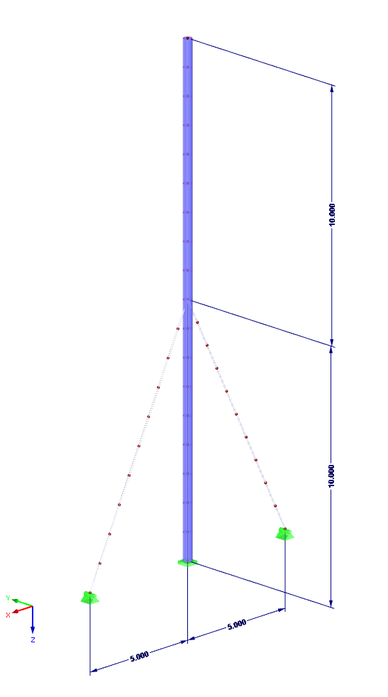
Lattice towers represent typical applications in steel construction. Examples of this special type of truss structure are antenna and overhead line towers, as well as columns for wind power stations, cable cars, and supporting frame constructions. The modeling can be done individually in RFEM and RSTAB by entering various tower elements. Furthermore, you can use different copy functions and parameterized input options. However, this procedure normally requires considerable effort. It is more convenient to model such structures using prefabricated catalog elements provided by the Block Manager. These elements are automatically stored in the database during program installation. Thus, you can use tower segments, platforms, antenna brackets, cable ducts, and so on as parameterized building blocks for generating diverse tower structures.
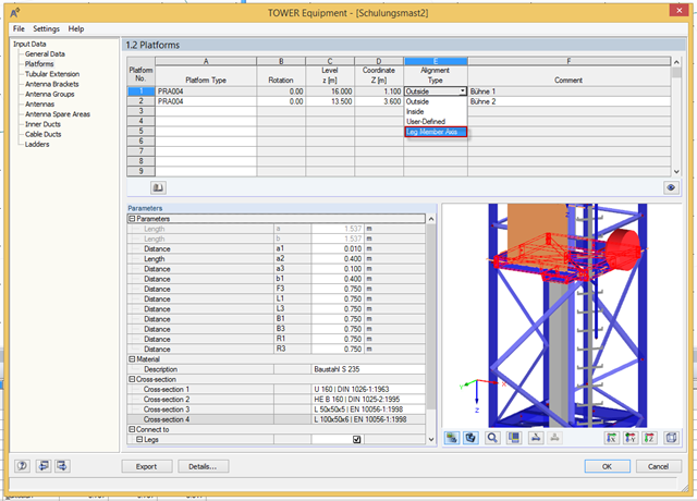
Platforms can be connected directly to leg members using the new "Leg Member Axis" option. Thus, it is no longer necessary to define the platform width or coupling member.
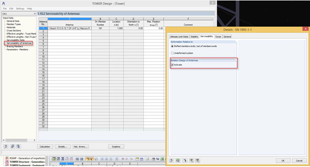
As of program version X.06.1103, you can perform serviceability limit state design checks of antennas in RF‑/TOWER Design. You can activate this function under [Details] → "Serviceability". Then, the limit values can be adjusted in Window 1.10.2, Serviceability of Antennas.
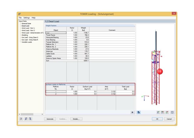
In the RFEM 5.04.0024 and RSTAB 8.04.0024 versions, there is a new feature in RF‑/TOWER Loading that allows you to define additional surface loads in a load case for dead loads; for example, from grids on platforms.
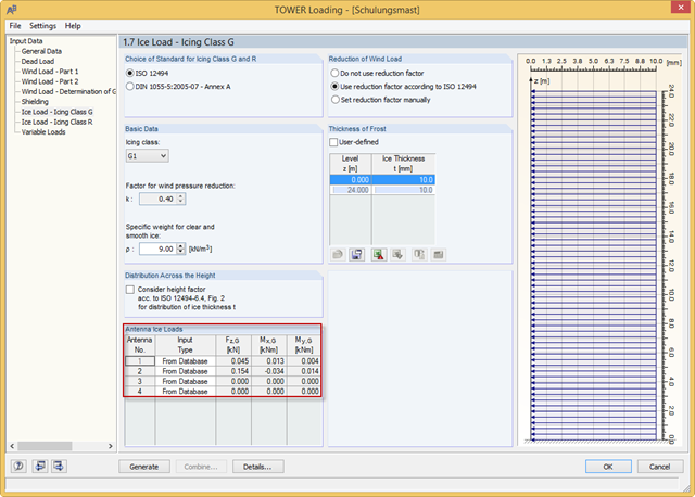
With the RFEM 5.04.0024 and RSTAB 8.04.0024 versions, you can define the antenna ice loads in RF‑/TOWER Loading. The program provides the values from the manufacturer databases. In addition, you can define the ice loads manually or use the calculation based on simplified geometry.
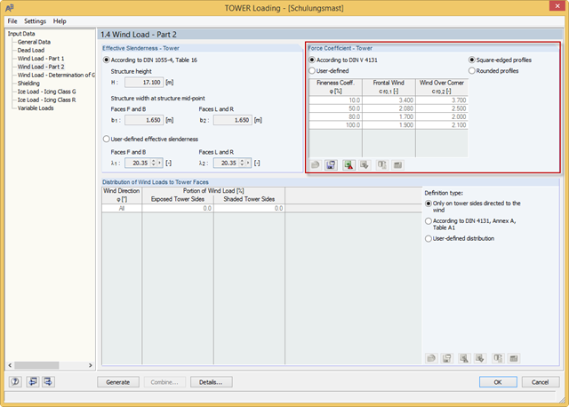
RF-/TOWER load was extended with force coefficients for rounded profiles of four-sided towers and square-edged profiles of three-sided towers. The force coefficients for rounded profiles are determined using the Reynolds number. Previously, you could only use the rounded profiles for four‑sided towers and the square‑edged profiles for three‑sided towers.