Creating User-Defined Antenna Bracket for RF-/TOWER Equipment
Technical Article
This article describes how to create a user-defined antenna bracket to be used in RF-/TOWER Equipment.
In general, the following points are particularly important when you create the antenna bracket:
- The first node that will be connected to the tower is node number 1.
- A member with cross-section 2 connects to this node. All other members that are connected to the tower must also have cross-section 2.
- Members to which antennas are to be attached have the cross-section number 1.
- General members without special properties have the cross-section 3.
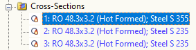
First, you create a new model and define the cross-sections 1 to 3.
Image 01 - Creating Cross-Sections
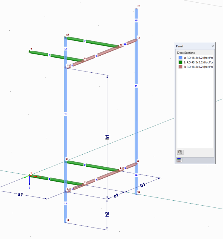
Afterwards, you create two members with cross-section 2, which will later be connected to two legs. The dimensions are not relevant, but should be based on a common tower.
Image 02 - Setting Connecting Members with Cross-Section 2
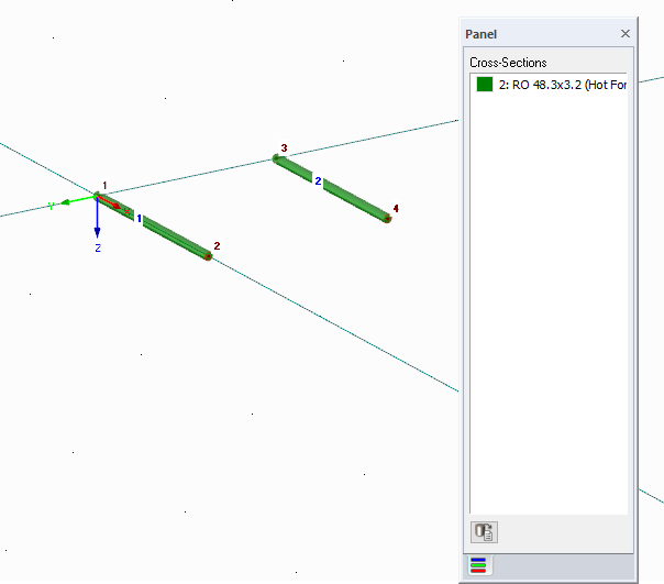
The next three members are general members without a special function and, therefore, have the cross-section number 3.
Image 03 - Setting Transverse Bars with Cross-Section 3
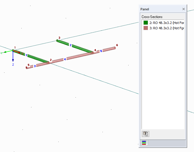
Copy all members to the top and create six members according to the following figure, to which antennas can be defined. These members are, therefore, cross-section 1.
Image 04 - Antenna Bracket with all Members
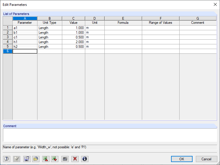
Since the antenna support should be used for any towers and masts with different dimensions, it is necessary to parameterize the nodes. To do so, create all the parameters in the first step. To open the corresponding dialog box, click the [Edit Parameters] button above the table. It is important that you do not use the parameters a and b, because they are already being used for the platforms and the basic geometry of the tower. It is not necessary to parameterize all the nodes. Assign five parameters for this antenna bracket.
Image 05 - Creating Parameters
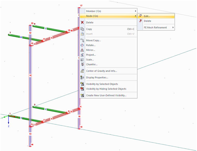
Assign the parameters by selecting single or multiple nodes and assign the parameters to the coordinates or a formula that uses the parameters.
Image 06 - Selecting all Nodes in Plane
Image 07 - Assigning Parameter a1 for all Nodes in Plane
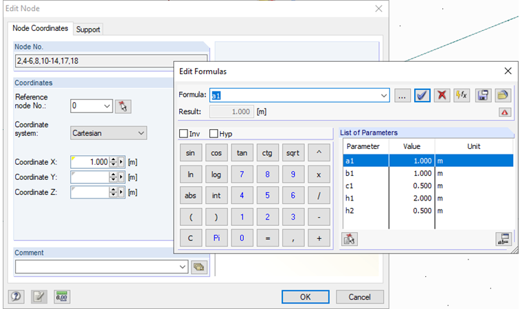
All coordinates that are parameterized have a yellow triangle in the respective cell, which makes the parametrization clearly visible. Thus, you can see in the table
to what extent the parameters have been assigned and, if necessary, correct errors more quickly.
Image 09 - Overview of all Parameterized Nodes
The following figure shows how the parameters are assigned.
Image 08 - Assigning Parameters
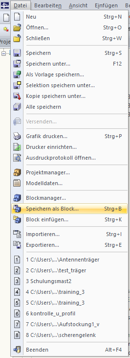
In the last step, select the entire model and save it as a block in the directory of the antenna brackets, either in 2D or 3D.
Image 10 - Saving Model as Block
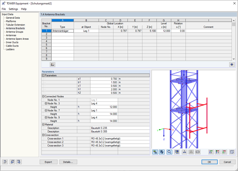
You can now open the antenna bracket and add it in the RF-/TOWER Equipment add-on module. You can adjust the parameters easily. You can also assign the antennas to the members with the cross-section 1 in the corresponding input window.
Author

Dipl.-Ing. Oliver Metzkes
Product Engineering & Customer Support
Mr. Metzkes is responsible for the development in the area of steel structures and provides technical support to our customers.
Keywords
Antenna bracket TOWER Equipment User-defined Customized Custom
Downloads
Links
Write Comment...
Write Comment...
Contact Us
Do you have any further questions or need advice? Contact us via phone, email, chat or forum or find suggested solutions and useful tips on our FAQ page, available 24/7.

Creating a User-Defined Platform for Use in RF-/TOWER Equipment
The following technical article describes the creation of a user-defined platform for use on a four-sided tower in the RF-/TOWER add-on modules.
For designs of tension stress, compression, bending stress, and shear force resistance, the maximum resistance design values are compared with the action design values. If structural components are subjected to both bending and compression at the same time, the RF-/TOWER Design add-on module performs an interaction. You can determine the factors according to Method 1 (Annex A) or Method 2 (Annex B).
For the flexural buckling design, it is not necessary to enter the slenderness ratio or the elastic critical buckling load of the governing buckling case. The module automatically performs calculation of all required factors for the bending stress design value. RF-/TOWER Design determines the effective critical moment for lateral-torsional buckling for each member on every x-location of the cross-section.
- How do I apply wind load on members of open structures?
- Is it also possible to use RF‑/TOWER Loading without the other TOWER add-on modules?
- When calculating a cable using the STEEL EC3 add‑on module, there is the error message "Incorrect characteristic stresses for material No. 1! Please correct this in Table 1.2."
- How can I create a drilled beam in RFEM?
- In connection with a calculation according to the large deformation analysis, I get significantly smaller deformations than for a calculation according to the linear static or second-order analysis. How is this possible?
- Which formula is used in the RF‑/TOWER Loading add-on module to calculate the first natural frequency for the determination of the structure coefficient?
- Is it possible to control the beam steering of an antenna in RF‑/TOWER Design?
- How can I control the wind load distribution on tower sides in the RF‑/TOWER Loading add-on module?
- Is it possible to use Dlubal Software for the calculation and design of 5G transmission masts, antenna masts, or towers?
- How is it possible to consider the real cross-section geometry of member elements in RWIND Simulation?
Associated Products