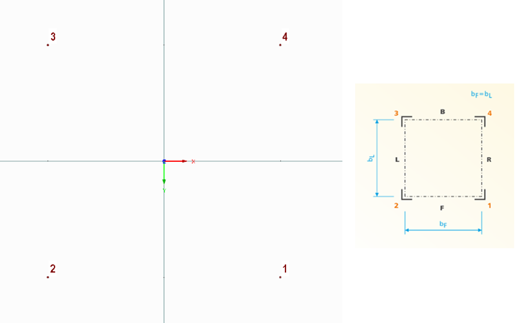
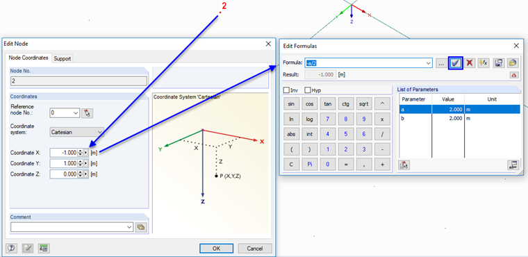
Node 1 lies in the positive quadrant, which means in the positive X- and Y-directions. Set the following nodes clockwise, so that node No. 4 is set in the negative Y-direction but in the positive X-direction. These four nodes will later be connected to corner posts one to four. The dimensions are not important now, but they should be square.
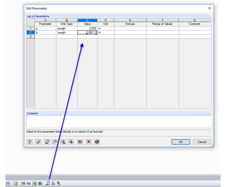
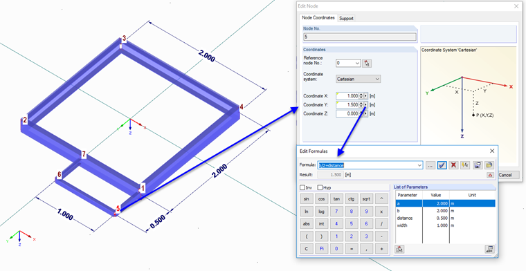
Afterwards, you have to parameterize nodes one to four so that they can be adjusted to the tower width in the add-on module.
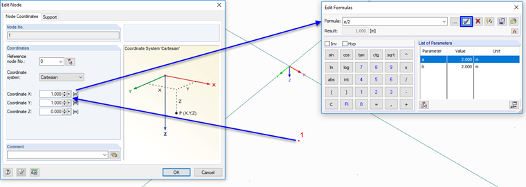
The width in the X-direction is defined as parameter "a", the width in the Y-direction as parameter "b".
In the following text, the node coordinates are assigned the parameters +/- a/2 b/2.
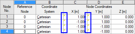
At the end, all four nodes must be parameterized for the coordinates X and Y. If everything is correct, all X- and Y-coordinates have a yellow triangle.
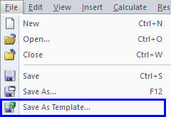
Note: At this point, it makes sense to save this model as a template for future user-defined platforms, as the steps will be the same up to this point. This template saves valuable time.
With this basis, it is now possible to set all members and entries of the platform. It is not absolutely necessary to parameterize all nodes from this point. It would, for example, be possible to define the correct model dimensions (nodes 1 to 4 must then be defined with the model dimensions as parameters) and then to import the platform 1:1.
However, if you want to import the platform to other towers and masts, it is also useful to use a consistent parametrization. The node numbering is no longer specified from this point, but it makes sense to follow a principle. For example, you could define the node numbers 10 to 19 on side F (+Y-direction), nodes 20 to 29 on side L (-X-direction), and so on. This way, it is easier to assign the antenna brackets, because a side can be assigned by means of the node number.
The platform shown in this example has been completely parameterized.
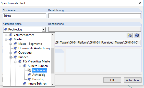
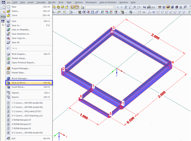
In the next step, the model is saved as a block in the corresponding folder of RF-/TOWER. To do this, select all elements and save them as a block.
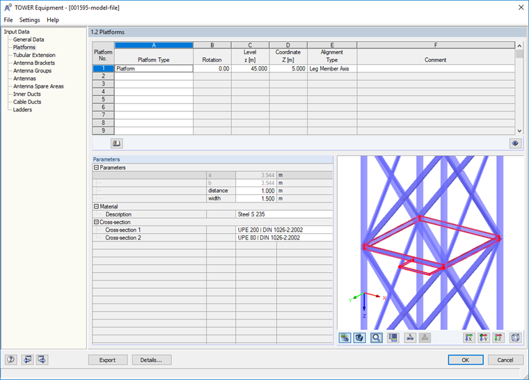
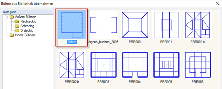
This platform can now be selected and inserted in each four-sided mast or tower from the library in RF-/TOWER Equipment.