93 Results
View Results:
Sort by:
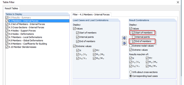
Sometimes, a detailed examination is needed of problematic areas of a joint or the stiffness of a frame joint. The following tips can help you with this. As an example, a frame joint was modeled using RF‑FRAME‑JOINT Pro and members, and used as a basis.

Diagonals of double angles are used for pipe bridge construction and for truss girders, among other things. They are usually subjected to tension, but it is necessary to transfer them in smaller compression forces with regard to the load application. In the case of slender diagonals in particular, you should also consider the bending due to self‑weight.
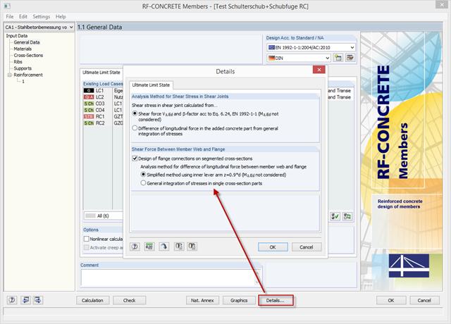
With the latest version of CONCRETE and RF-CONCRETE Members, it is possible to perform shear design for the connection of compression and tension flanges on a T-beam web.
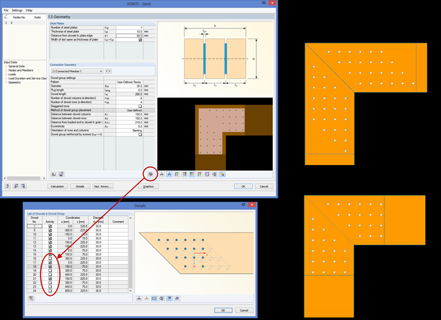
In RF‑/JOINTS Timber, you can remove an individual dowel from the calculation, thus creating any dowel layout. The calculation disregards these removed dowels for the ultimate limit state design, as well as for the net timber cross‑section analysis and the rotational spring stiffness determination.
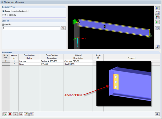
In RF-/JOINTS Steel - Pinned, it is possible to design connections without a supporting structure (for example, columns). In this case, the beam is connected to an anchor plate. How is this kind of connection defined?
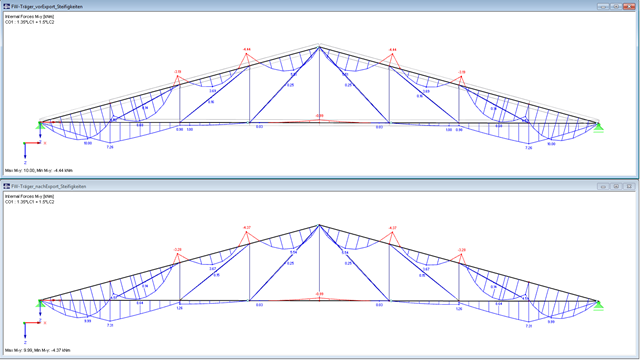
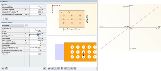
In RF-/JOINTS Timber - Steel to Timber, you can consider the eccentricities of a connection during the calculation. The figure shows different internal forces without consideration of the eccentricity (above) and withn consideration of the eccentricity (below).
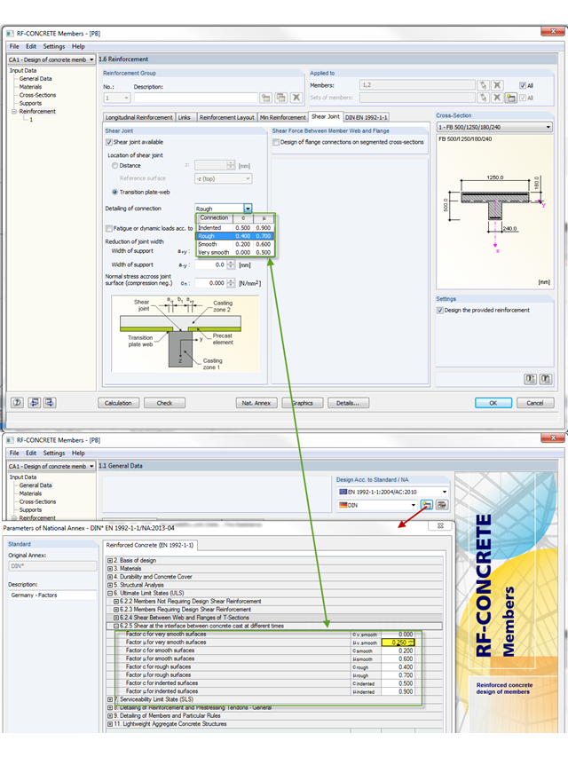
The shear resistance design value of a joint depends mainly on the formation or the roughness of the connection. When determining the ultimate limit state, this is considered by the factors µ (friction) and c (adhesion percentage of the contact area of the composite concrete).
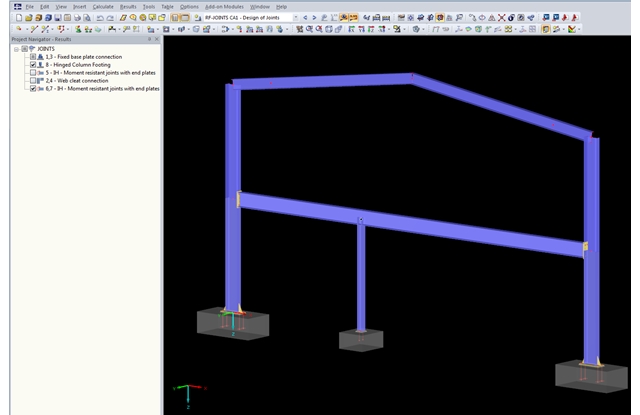
The updated Results Navigator of RF‑JOINTS allows you to display the results of different module cases simultaneously. Thus, you can display all column base designs at the same time in order to perform collision checks of the foundations, for example.

For structural reasons, shear connections usually include fin plates or flange angles. Main and secondary beams arranged on the top edge require notching or long fin plates. Hinged end plate connections are often welded to the web.
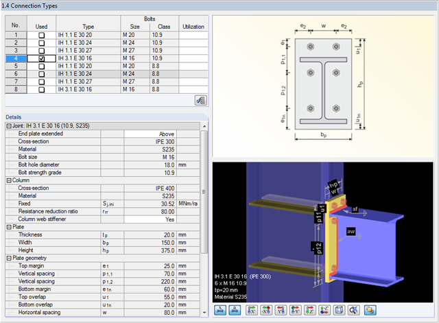
Starting with version X.05.0018, you can also analyze moment-resistant beam-column connections in RF‑/JOINTS Steel - DSTV. Both single-sided and double-sided connections are possible. In compliance with the DSTV guidelines, the program checks (with respect to the loading) whether the existing column cross‑section is dimensioned sufficiently. Optionally, you can transfer the rotational stiffness and the eccentricity of the connection to RFEM or RSTAB.
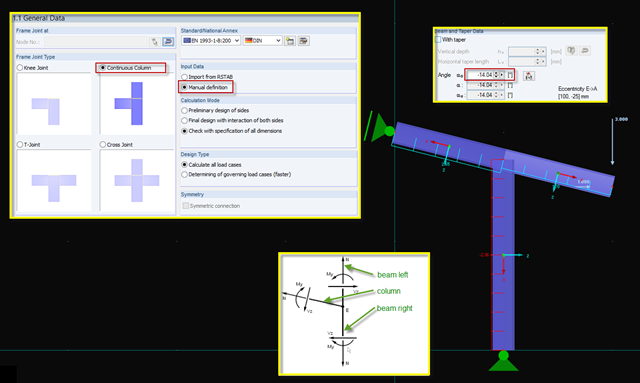
Since no automated frame joints of the "continuous beam" type are included in RF‑/FRAME‑JOINT Pro, you can use another option for designing this type. Designing this kind of beam combination is possible using manual definition and the "Continuous Column" type.
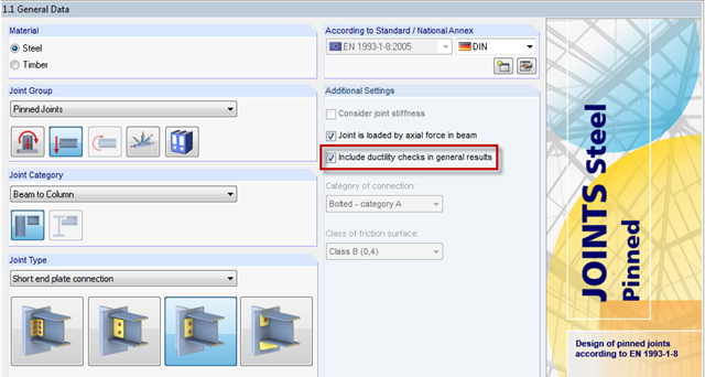
RF-/JOINTS Steel - Pinned has the default option "Include ductility checks in general results". What does this mean?
To obtain forces for designing surface connections, you can look at the results using the "Result diagram" function of a connection line. Among other things, there are auxiliary tools such as "Average line" and "Average region".
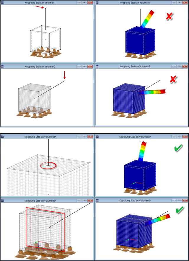
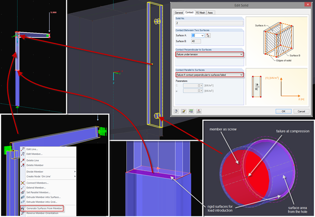
If a slender component (member) is to be connected to a massive component (solid), it is necessary to pay attention to the correct connection of both elements.
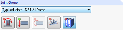
Starting with program version X.06, joint groups are clearly identified in RF‑/JOINTS.
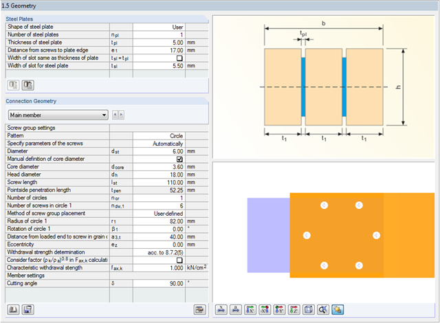
In RF-/JOINTS Timber – Steel to Timber, you can select a circular connection type for the dowel, bolt, nail, and screw joint categories. For this connection type, the minimum radius is set in compliance with the recommendations of the STEP-1 report of the German Information Service Timber.

As of the program version X.06 of the RF‑/TIMBER Pro, RF‑/TIMBER AWC, and RF‑/TIMBER CSA add‑on modules, notches and cross‑section reductions can be considered in the design. The procedure is as follows:
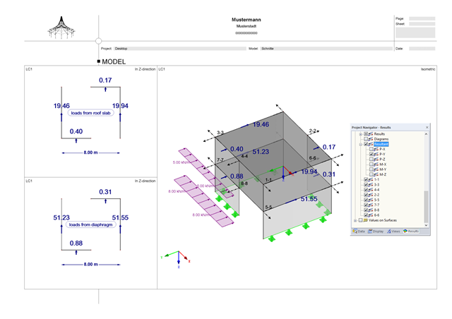
A successful project process involves not only the building owner and the engineer, but also the designers. These days, they also have to design standard connections in steel structures themselves. To do this, the corresponding internal forces of connections are required.
In RF-JOINTS Timber – Steel to Timber, you can consider the possible minimum slippage of bolts in the case of guide pins. In RFEM, this slippage is taken into account using the flexibility in member end releases.
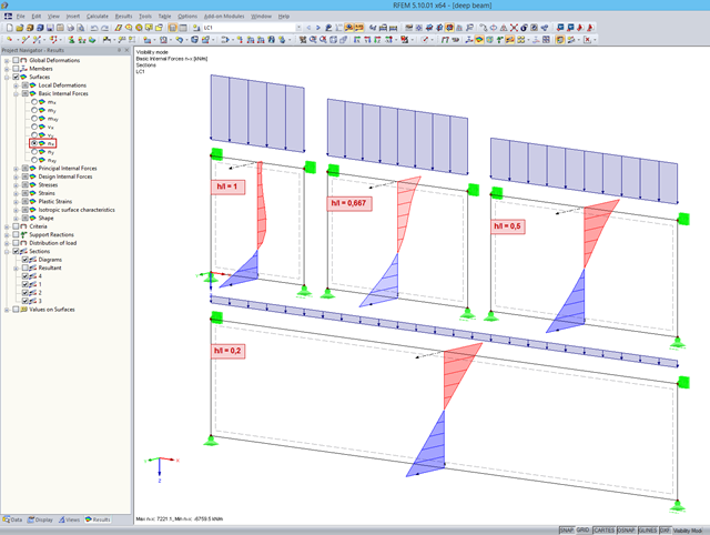
When analyzing structural components of reinforced concrete structures, it is often necessary to design deep beams. These are mainly used for window and door lintels, upstand and downstand beams, the connection between split-level slabs, and frame systems. If they are displayed as surfaces in RFEM, the evaluation of reinforcement results requires further steps.