11 Results
View Results:
Sort by:

This article discusses the options available for determining the nominal flexural strength, Mnlb for the limit state of local buckling when designing according to the 2020 Aluminum Design Manual.

Table 3.1 of EN 1993‑1‑8:2010‑12 defines the nominal values of the yield strength and the ultimate limit strength of bolts. The bolt classes given here are 4.6, 4.8, 5.6, 5.8, 6.8, 8.8, 10.9. The note for this table states that the National Annex may exclude certain bolt classes. For the NA of Germany, these are the bolt classes 4.8, 5.8, and 6.8.

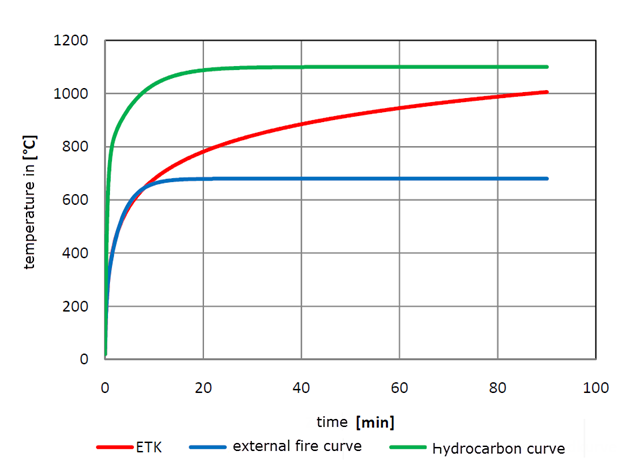
With RF-/STEEL EC3, you can utilize nominal temperature-time curves in RFEM and RSTAB. The standard time-temperature curve (ETK), the external fire curve and the hydrocarbon fire curve are implemented. Moreover, the program provides the option to directly specify the final temperature of steel.
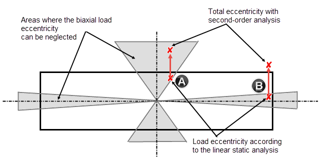
Daily tasks in reinforced concrete design also include designing compression elements subjected to biaxial bending. The following article describes the different methods according to Chapter 5.8.9, EN 1992-1-1, which can be used to design compression elements with biaxial load eccentricities by means of the nominal curvature method according to 5.8.8.
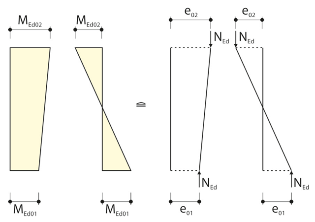
When calculating the internal forces for the buckling analysis with the method based on nominal curvature in RF‑CONCRETE Columns, the required eccentricities have to be determined.
You can apply nominal temperature‑time curves in RFEM or RSTAB using RF‑/STEEL EC3. For this, the standard time-temperature curve (ETK), the external fire curve and the hydrocarbon fire curve are implemented in the program. Based on these temperature curves, the add‑on module can calculate the temperature in the steel cross‑section and thus perform the fire design using the determined temperatures. This article explains the thermal behavior of structural steel, as this has a direct impact on the calculation of component temperatures in RF‑/STEEL EC3.
![Section Factor Am/V for Unprotected Steel Components (Source: [5])](/en/webimage/009429/2418748/01-en-1-png.png?mw=640&hash=0fa099ecd1abc5310bef76fe3f22b7fe0c925df6)
Using RF-/STEEL EC3, you can apply nominal temperature-time curves in RFEM or RSTAB. For this, the standard time-temperature curve (ETK), the external fire curve, and the hydrocarbon fire curve are implemented in the program. Based on these diagrams, the add-on module can calculate the temperature in the steel cross-section and thus perform the fire design. This article explains the behavior of protected and unprotected steel cross‑sections.
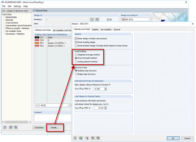
If an aluminum member section is comprised of slender elements, failure can occur due to the local buckling of the flanges or webs before the member can reach full strength. In the add-on module RF-/ALUMINUM ADM, there are now three options for determining the nominal flexural strength for the limit state of local buckling, Mnlb, from Section F.3 in the 2015 Aluminum Design Manual. The three options include sections F.3.1 Weighted Average Method, F.3.2 Direct Strength Method, and F.3.3 Limiting Element Method.
Using RF-/STEEL EC3, you can apply nominal temperature-time curves in RFEM or RSTAB. The standard time-temperature curve (ETK), the external fire curve and the hydrocarbon fire curve are implemented. Moreover, the program provides the option to directly specify the final temperature of steel. This steel temperature can be calculated using the parametric temperature-time curve, as described in the Annex to DIN EN 1992-1-2. The different fire exposures are explained in this article.
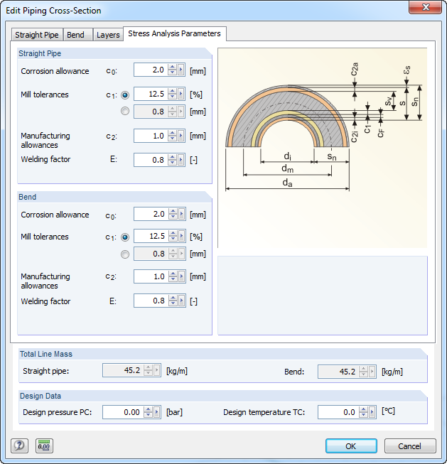
For stress calculations, some standards use the "wall thickness analysis". We get the wall thickness by subtracting corrosion, abrasion allowance, manufacturing allowances (threading, grooving, and so on), and mill tolerances from the nominal wall thickness. All necessary values can be entered in the "Piping Cross‑Section" dialog box, "Stress Analysis Parameters" tab.
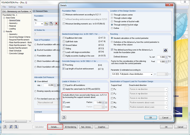
In RFEM and RSTAB, the internal forces of individual load combinations are determined according to the second-order analysis by default. If you use the RF‑CONCRETE add‑on module for stability analysis of reinforced concrete columns, you can change the calculation method of LCs to the linear static analysis, since the effects of the second‑order analysis are already considered in the calculation according to the model column method in RF‑CONCRETE Columns (nominal curvature method).