


General
The RF-/CONCRETE Columns add-on module designs reinforced concrete compression elements by means of the nominal curvature method as described in Eurocode 2, Chapter 5.8.8. Other standards describe this method as the model column method. A previous article describes in detail the determination of load eccentricities that have to be applied when using the nominal curvature method. For this reason, determining single eccentricities will not be described in detail here.
Separate Design in Direction of Principal Axis Without Considering Biaxial Moment Interaction
According to 5.8.9 (2), EN 1992-1-1 [1], a column with biaxial load eccentricity may be designed separately in both principal axis directions without considering the moment interaction if the limits of Equations 5.38a and 5.38b [1] are complied with. The equations are described in the linked article above. These limits and the design approach are based on the fact that one of the two load eccentricities represents the dominant value and the second represents the subordinate value.
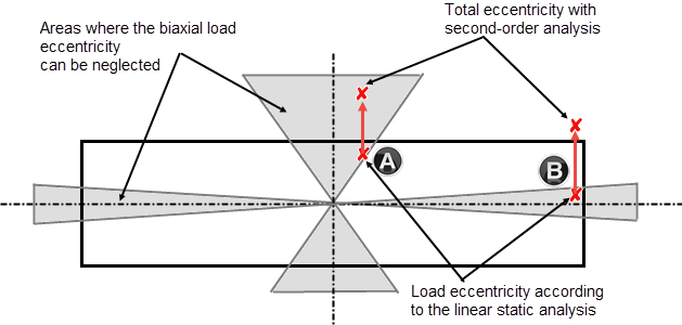
When designing in the separate principal axis directions, the additional eccentricity from imperfection must be considered only in the dominant direction, which means in the governing direction. Image 01 shows which areas do not have to be considered for the biaxial bending. If the eccentric axial force is in the shaded areas, you can design the column separately in both principal directions. Please note that the load eccentricities have to be considered according to the second-order analysis in the respective principal axis directions.
This is also shown in Image 01. Points A and B in Image 01 symbolize two examples of a possible load position where the influence of eccentricity according to the second-order analysis has different effects. Without taking into account the second-order analysis (e2), both points are located in the shaded and allowable areas in which the biaxial bending design can be neglected. When considering the eccentricity according to the second-order analysis, the biaxial load eccentricity is reduced for point A, whereas for load position B, biaxial bending is increased and the load is shifted out of the allowable range.
Separate Design in Direction of Principal Axis Considering Biaxial Moment Interaction
If the conditions of Equation 5.38a and Equation 5.38b [1] are not fulfilled, the prerequisites for the separate design in the principal axis direction without considering the biaxial moment interaction according to 5.8.9 (2) are not met. Section (4) of Chapter 5.8.9 [1] provides a simplified approach with Equation 5.39 which you can use to consider the biaxial moment interaction with prior design of the individual principal axis directions.
The following Equation 5.39 [1] takes the moment interaction into account in a simplified way.
|
MEd,z/y |
Bemessungsmoment um die entsprechende Achse einschließlich des Moments nach Theorie II. Ordnung |
|
MRd,z/y |
Biegewiderstand um die entsprechende Achse |
|
a |
= 2 für runde und elliptische Querschnitte, gemäß Bild 02 für rechteckige Querschnitte |
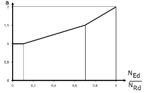
Image 02 shows exponent a as a function of the ratio NEd/NRd. NRd is the design value of the centric axial resistance and can be determined with NRd = Ac ⋅ fcd + As + fyd. Ac represents the gross cross-section area, As the longitudinal reinforcement area, and fcd and fyd the design strengths of the materials used.
When using Equation 5.39 [1], it should also be noted that the two bending resistances MRdy and MRdz subjected to a constant axial force are taken from the design interaction diagrams for the two principal directions (see Image 03).
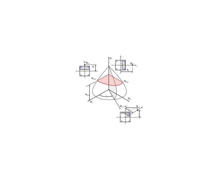
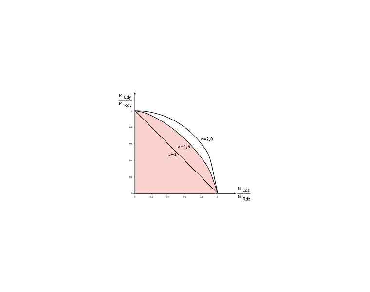
Image 03 shows a quadrant of a three-dimensional My-Mz-N interaction diagram. Equation 5.39 is based on simplifying a horizontal section at NEd using the 3D interaction diagram and generating a simplified My-Mz moment interaction diagram with exponent a. In Image 03, the actual My-Mz moment interaction diagram for the axial force NEd (horizontal section) is shown shaded in red. The simplified interaction diagram according to Equation 5.39 is also red-shaded for comparison. Image 04 shows, depending on exponent a, the distribution of the moment interaction applied in Equation 5.39 [1].
The advantage of this simplified approach according to Equation 5.39 [1] is that compression elements with biaxial eccentricities can also be designed quickly and easily by means of the known M-N interaction diagrams for uniaxial bending with axial force.
Exact Design of Cross-Section with Biaxial Load Eccentricity
A precise design of a cross-section with axial force and biaxial bending requires an iterative calculation of the cross-section strains. The calculation of these cross-section strains is only possible with a calculation tool. The ultimate limit state design is fulfilled if the loading is within the Mres-N interaction diagram (gray-shaded area in Image 03) or in the exactly determined Mz-My moment diagram (red-shaded area in Image 03). By precisely determining the limit curves, you can generate additional load capacities for the design.
Conclusion
For a biaxial load eccentricity, the standard allows different design variants depending on the load position. By respecting the boundary conditions of Equations 5.38a and 5.38b [1], the biaxial moment interaction can be neglected and the design can be carried out in the principal axis directions. If the limits mentioned above are exceeded, the moment interaction must be considered in the design. This is possible in a simplified way with the interaction formula according to Equation 5.39 [1] or by means of an accurate biaxial cross-section analysis. All the described design approaches are possible with the RF-/CONCRETE Columns add-on module.