25 Results
View Results:
Sort by:

Everything is online. The same is true for the Dlubal licenses for RFEM 6, RSTAB 9, and RSECTION. This article contains information about using and managing online licenses, reserving licenses, checking the license validity, and moving authorizations between the licenses.

When a concrete slab is set upon the top flange, its effect is like a lateral support (composite construction), preventing problems of torsional buckling stability. If there is a negative distribution of the bending moment, the bottom flange is subjected to compression and the top flange is under tension. If the lateral support given by the stiffness of the web is insufficient, the angle between the bottom flange and the web intersection line is variable in this case so that there is a possibility of distortional buckling for the bottom flange.

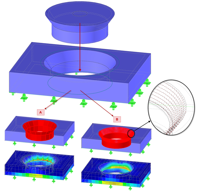
The punching shear design, in line with EN 1992-1-1, should be performed for slabs with a concentrated load or reaction. The node where the design of punching shear resistance is performed (that is, where there is a punching problem) is called a node of punching shear. The concentrated load at these nodes can be introduced by columns, concentrated force, or nodal supports. The end of the linear load introduction on slabs is also regarded as a concentrated load and therefore, the shear resistance at wall ends, wall corners, and ends or corners of line loads and line supports should be controlled as well.

In RFEM 5 and RSTAB 8, you can save problems and warnings occurring during the model check as an extra view. This way, you can easily work through the hints and messages, one after the other, cleaning the model. The function is available for double nodes, overlapping members/lines, and surfaces.
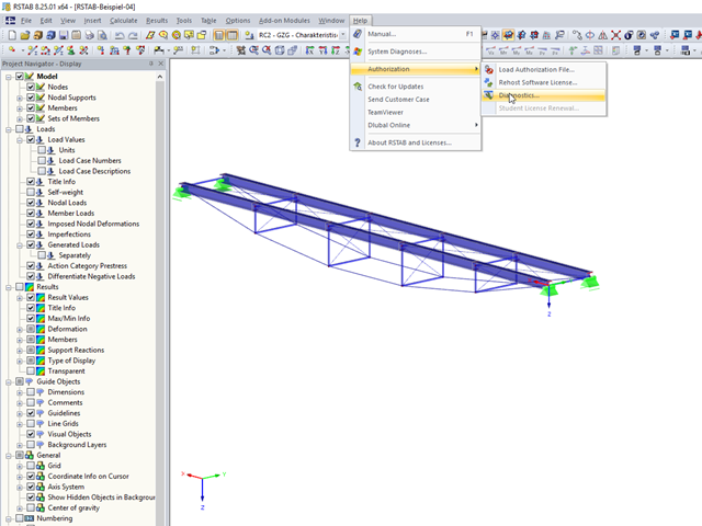
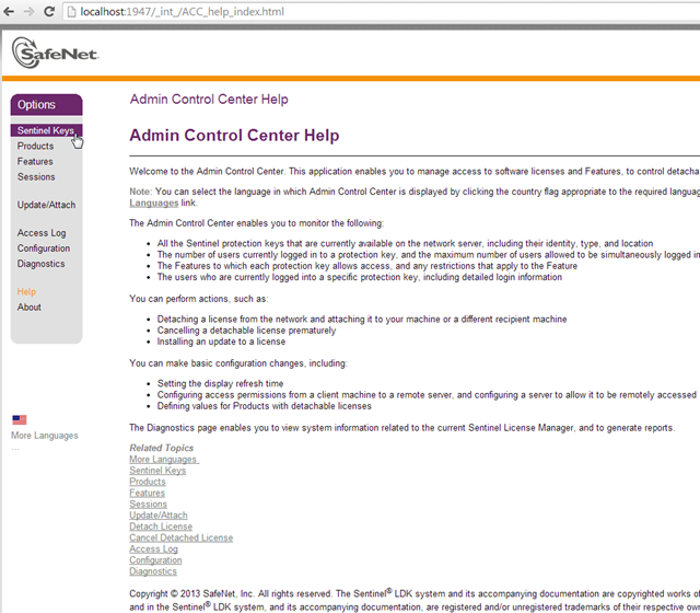
In RFEM 5 and RSTAB 8, you can view detailed information on the currently used license and installed dongle driver. In case of any problems with the license, you can send the created text file to the Dlubal Software hotline, which allows us to provide you with a fast and efficient analysis. To create the file, select "Help" → "Authorization" → "Diagnostics".
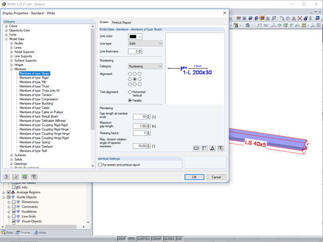
In the case of large models, it is often problematic when the cross‑section descriptions are displayed horizontally or vertically to a member.

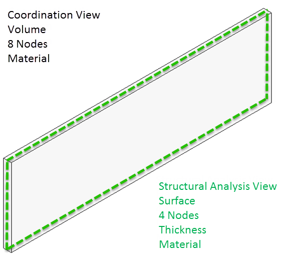
For cross‑laminated structures with large spans, downstand beams or hybrid structures are often used. They can be modeled in RFEM 5 by using surfaces and member cross‑sections. In both structural systems, curved downstand beams are also possible without any problems. In the case of the curved surface, the member is always appropriately generated by means of the automatic member eccentricity with the thickness distance of the surface and the member. The downstand beam can also be connected flexibly by means of a line release.
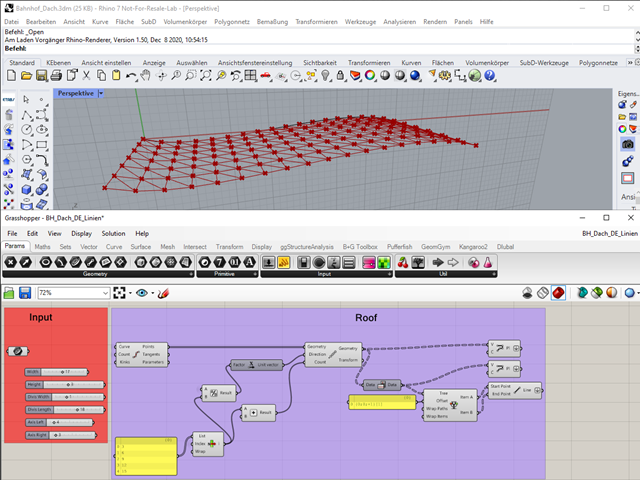
"A good tool is half the job done": This proverb could be applied equally to the software industry. The more a program is task-tailored, the more efficiently the tasks can be solved. The variety and complexity of today's problems, especially in structural engineering, require specifically tailored solutions. Creating your own programs by means of textual programming requires in-depth knowledge and a great ability to abstract. Understandably, only very few engineering offices face this challenge. For this reason, there are additional software solutions providing the user with a visual development environment.
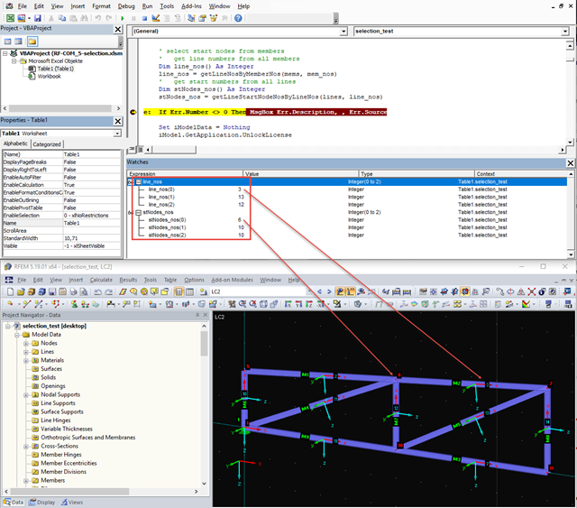
When editing elements via the COM interface, selecting elements is often a problem because it cannot be carried out visually via the work window. The selection can be particularly difficult for models that have been created via the program interface and are then to be modified using a separate program. Apart from the exception, when the selection was made previously via RFEM, there are several alternatives for programming.
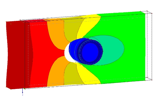
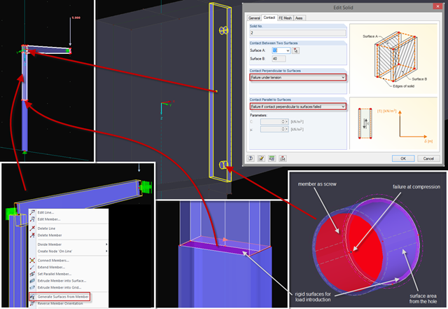
The definition of the non-linear contact problem plays an important role for more detailed investigations of shear/hole bearing connections or their immediate environment. This article uses a solid model to search for comparable and simplified surface models.

Shell buckling is considered to be the most recent and least explored stability issue of structural engineering. This is due less to a lack of research activities than to the complexity of the theory. With the introduction and further development of the finite element method in structural engineering practice, some engineers no longer have to deal with the complicated theory of shell buckling. Evidence of the problems and errors to which this gives rise is very well summarized in [1].
In the BIM workflow, IFC files are frequently used as the basis for data exchange between CAD and structural engineering software. However, there is a fundamental problem with this approach. This article explains various types of IFC files and provides an overview of the import and export options in Dlubal Software programs.
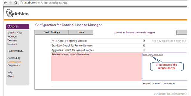
The network licenses of Dlubal Software provide a very convenient solution for engineering offices as well as for users who are often on the move. This can be helpful if you are in a consulting meeting with a building owner and want to directly apply the current changes and show the solution immediately. You only need an Internet and a VPN connection in your office to access all your purchased licenses.
The current state of the development of finite element analysis software and computer technology allows for the calculation of more complex structure. More and more frequently, FE calculations are performed on the entire model. In this context, certain practical construction problems may appear. One of these problems is the consideration of a construction process in the model.
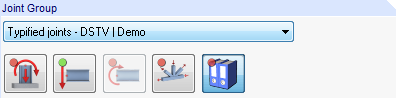
Starting with program version X.06, joint groups are clearly identified in RF‑/JOINTS.
Contact solids can be created between two flat surfaces or between two cylindrical shells. However, if the area of the contact problem is a little more complicated, it is necessary either to simplify the system so that the requirements of a contact solid can be met, or to go back to the "old" modeling style using a rod model.
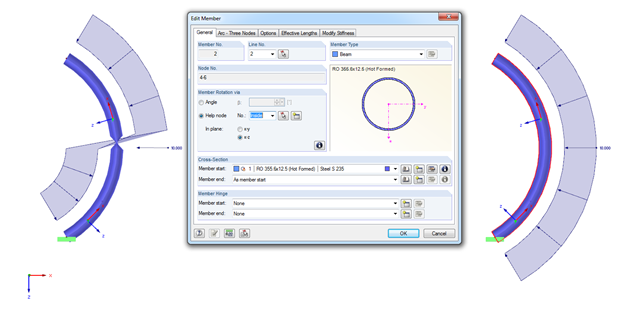
When modeling arc-shaped members, the problem shown in the figure may occur. It seems as if the member cross‑section is twisted or the load applied on the local z‑axis changes direction. How does this come about?

Dlubal Software provides students with the complete range of its products free of charge during their studies. The licensing is done by a softlock, taking into account the following.
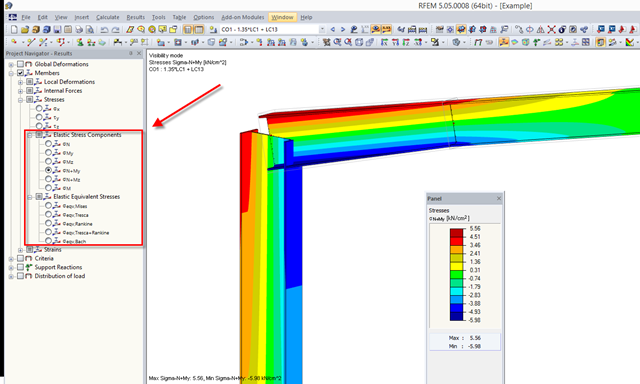
RFEM 5.04.xx allows for graphical visualization of normal and shear stress of members (this feature is available only if the RF‑STEEL add‑on module is licensed).
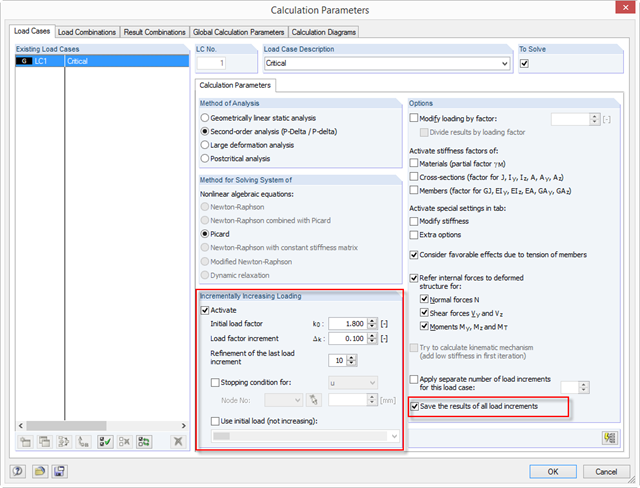
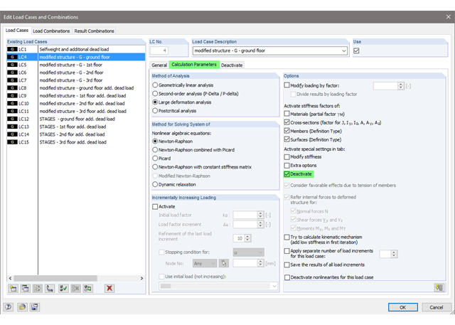
With RFEM 5.04, there are new options for the system analysis (critical load factors) of load cases and load combinations in the calculation parameters of the RF‑STABILITY add‑on module: ~ The load increment is not closed due to stability problems, but optionally also due to predetermined deformation limits. ~ The calculation method is applicable to all nonlinear calculations. ~ You can define an initial load (LC/CO) that is not increased (for example, self-weight). ~ The "Refinement of the last load increment" option provides an efficient option to determine the critical load factor as precisely as possible.
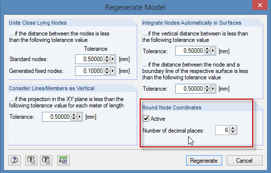
During the cooperation between the structural and design engineers, the DXF format is often used if there is no direct interface. However, the geometrical data of these DXF files are not always accurate. For example, an inaccuracy in the third decimal place is not noticeable, but it can lead to numerical problems when generating the FE mesh in RFEM.
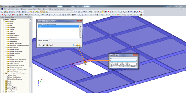
A modell check allows you to find overlapping members, among other things. However, this targeted selection could cause some minor problems. Therefore, there is a selection window now available, which appears when you click on one of the elements. This appears by clicking on one of the elements. Additional information helps you to select the correct member.
Sometimes, a detailed examination is needed of problematic areas of a joint or the stiffness of a frame joint. The following tips can help you with this. As an example, a frame joint was modeled using RF‑FRAME‑JOINT Pro and members, and used as a basis.
A network dongle is the appropriate solution to ensure security for licensing within companies working with several RFEM and/or RSTAB licenses. First, the dongle is placed on a central server. The licenses are then requested by RFEM and RSTAB, as well as all other stand-alone programs, from this dongle via the network.
Extensive calculations may result in vast amounts of data. Of course, current hard drives and SSDs are measured in terabytes. Therefore, you expect this to be no problem for current computing technology. This is true, in fact, but as often happens, the devil is in the details.