


In this article, we also highly recommend not simply creating a single FE model for each steel shell, setting up loads, then pressing "Calculate". In most cases, this procedure leads to additional work, as numerous analytical methods for the verification are available for simple cases that are common in design practice. These analytical methods, the hand calculation formulas, also have the great advantage of space-saving and simple documentation. For some containers, the plate buckling analysis can be performed on an A4 page. Such space-saving documentation is not possible with an FE analysis.
However, there are also numerous cases where the use of a finite element analysis makes sense and should be preferred over a manual calculation. The following points are just a few examples of cases where it makes sense to use an FE calculation:
In the following text, the buckling design of a steel shell is performed using RFEM according to the MNA/LBA concept. Thus, nonlinear material behavior of the steel is applied.
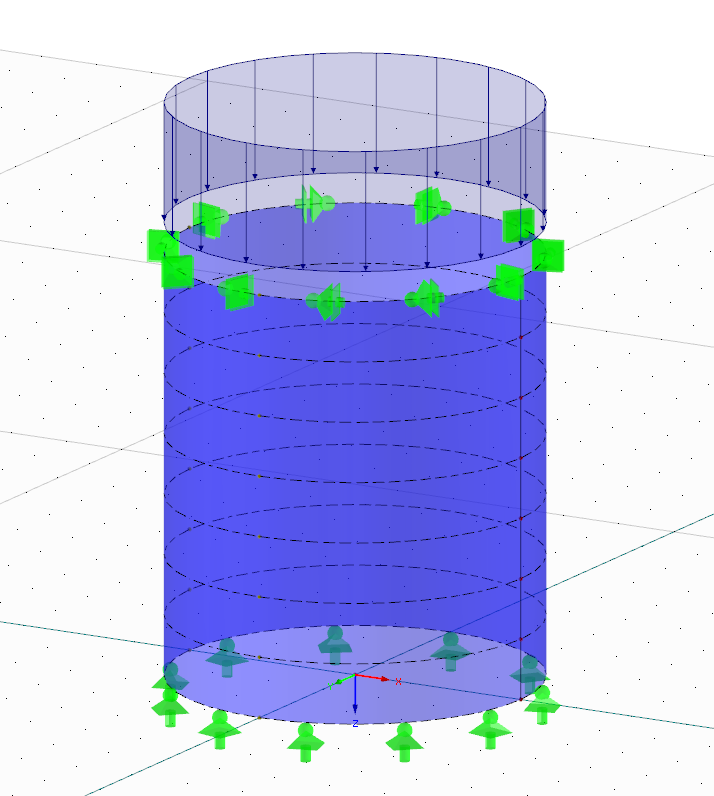
Plate Buckling Analysis According to EN 1993-1-6
In EN 1993-1-6, three options are presented for performing a plate buckling analysis for steel shells. In this section, they are to be briefly listed and evaluated with regard to the requirements of computing technology, as well as with regard to the requirements placed on the designing engineer.
Stress-Based Plate Buckling Analysis
Stress-based plate buckling analysis is considered to be the standard analysis method that almost every engineer has used when performing shell design. An expert engineer classifies this method as easy and the computing requirements are either very low or non-existent, as formulas for manual calculation are frequently used.
A major problem of this analysis method is that economical results will be hardly achieved for shell structures with load situations that deviate considerably from the standard buckling modes. In addition, as a user of this concept, you are set on the wrong track by this method, because you could easily think that the plate buckling safety of the shell structure only depends on the occurring stresses. If that were the case, the stiffening of a shell wall by, for example, longitudinal ribs would have little benefit, as this does not significantly reduce stresses. In reality, the plate buckling safety of a skilfully stiffened shell is much higher than that of an unbraced shell of the same wall thickness.
Plate Buckling Analysis Based on Numerical Calculation by Means of Global MNA/LBA Calculation
This method will be used for the following shell design. An MNA/LBA calculation certainly requires that the user have somewhat more background knowledge in shell stability than is the case for the stress-based design method. Moreover, the computing technique should be more powerful, since a linear elastic bifurcation analysis (LBA) and a material nonlinear analysis (MNA) have to be performed for correct application of this method.
In the author's view, this design method is the most effective way to perform plate buckling analysis if the calculation is to be carried out using the FE analysis. The justification for this is that for a design using the MNA/LBA concept, the computing technology is consistently used without expecting too much effort from the user. If the internal forces of the shell are calculated linear elastic to use them for the stress-based plate buckling analysis, the computer technology will be used too inconsistently, as powerful programs such as RFEM are also able to determine the load-bearing capacity of the shell structure.
Plate Buckling Analysis Based on Numerical Calculation by Means of Global GMNIA Calculation
A GMNIA analysis to determine sufficient shell stability is probably the most consistent method of plate buckling analysis. The internal forces are thus calculated geometrically and materially non-linearly, using imperfections.
This method requires excellent background knowledge on shell stability from the user, as, among other things, the correct approach of imperfections (pre-buckling) is very difficult. If the user does not have this background knowledge, the design process with the GMNIA concept should be avoided in any case. Moreover, substantial demands are placed on the computer technology when using this method. Thus, the program system used must be able to perform a bifurcation analysis for each load step of the nonlinear analysis to, where appropriate, detect a "jump" from the subcritical pre-buckling path to the supercritical post-buckling path.
This concept will not be explained further here, since, in the author's view, it has little significance for the design practice. For more information, please refer to the article by Herbert Schmidt [2] in the Steel Construction Calendar of 2012, which gives a good overview of the difficulties faced when using the design according to the GMNIA method.
Example of Plate Buckling Analysis Using the MNA/LBA Method
Input of Structural System
The steel shell shown in Figure 01 will be designed for buckling. In principle, this structure is a typical case where an engineer familiar with the design of steel shells would hardly consider an FE analysis. Since the principal aim of this article is to familiarize the reader with the topic of plate buckling analysis according to the MNA/LBA concept, an example will be used that is as simple as possible.
An important topic in nonlinear calculations or bifurcation analyses of shell structures is the element size, since unfavorably selected FE mesh settings can lead to falsified results. In specialized literature, various formulas for rough calculation exist for this, where the (small) convergence study is the most appropriate approach.
Calculation with RFEM
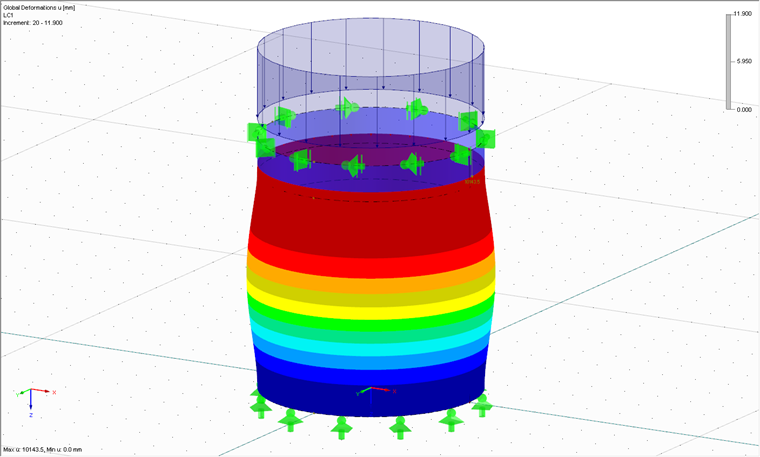
After model and load input and selecting suitable FE mesh settings, the calculation with RFEM can start. First, the material nonlinear analysis is performed. The aim of this analysis is the plastic reference resistance (that is, the critical load factor at which the entire shell would fail plastically). The RF-MAT NL add-on module is ideally used, as only nonlinear material properties are then available in RFEM. Alternatively, a linear elastic calculation can be carried out; then the plastic reference resistance can be approximately calculated using formula (8.24) from [3]. Figure 02 shows the deformed system after reaching the plastic reference resistance rRpl = 11.90.
Subsequently, the linear bifurcation analysis is performed where the sequence was arbitrarily chosen here. It is also possible to perform this analysis first, then continue with the MNA method. The aim of the linear bifurcation analysis is also to obtain a critical load factor, but this time one which would cause the buckling of the perfect shell. This requires the RF-STABILITY add-on module, with which linear bifurcation analyses and geometrically nonlinear calculations can be performed. This does not refer to GMNIA calculations. Figure 03 shows the first mode shape of the considered shell for the eigenvalue of rRcr = 7.70.
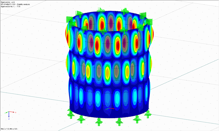
Plate Buckling Analysis
The plate buckling analysis is shown as a whole in the following text. Special attention is to be paid to the four independent buckling parameters, which can be determined for most practical construction cases according to Annex D in [3].
Plastic reference resistance from the MNA:
rRpl = 11.9
Critical load factor from the LBA:
rRcr = 7.70
Slenderness degree:
Elastic imperfection factor:
Plastic multiplying factor:
βov = 0.60
Buckling curve exponent:
ηov = 0.60
Fully plastic limiting degree of slenderness:
Partially plastic limiting slenderness:
Buckling reduction factor:
Plate buckling analysis:
The main issue of the design is to classify the results obtained by the program into one of the typical buckling cases. In the present case, it is very simple due to the loading: It is about pure meridian pressure buckling. Thus, the independent buckling parameters according to Annex D 1.2 in EN 1993-1-6 [3] are calculated.
The result of the plate buckling analysis according to the MNA/LBA method is a critical load factor. In the example shown here, it is 1.515. This means: The load of the shell could be increased more than 50%.
If the analysis is based on the stress-based concept, this would result in a critical load factor of 1.398, which shows that for typical buckling cases, such as the meridian pressure buckling considered here, no additional benefits are gained by the numerically based plate buckling analysis according to the MNA/LBA method. It should be noted, as already mentioned, that this is different as soon as local load introductions or supports lead to stress concentrations.
Conclusion
Modern, powerful, and user-friendly FEM programs such as RFEM significantly facilitate the work of a calculating engineer when performing the design of the sufficient buckling safety of a shell. As a result of the more consistent use of computer technology in the MN /LBA concept, more realistic and therefore more economical results can generally be achieved.
It should also be mentioned that an FE analysis is not advisable for every shell structure, as good analytical methods are available for typical buckling cases, which can lead to reduced documentation and to similarly economical results. However, if the engineer encounters cases in the design practice that cannot be assigned to a typical buckling case, an FE analysis according to the MNA/ LBA concept with RFEM with the RF-STABILITY and RF-MAT NL add-on modules is a real alternative to the standard methods.