11 Results
View Results:
Sort by:
Warning Regarding Connection to Project
---
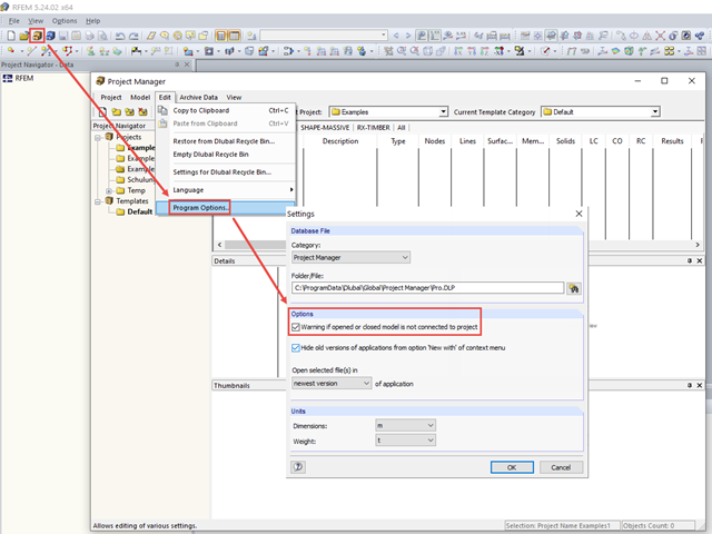
When opening a model immediately after opening the program, there is a message window asking if you want to create a new project for the model in the Project Manager.

In RFEM 5 and RSTAB 8, you can save problems and warnings occurring during the model check as an extra view. This way, you can easily work through the hints and messages, one after the other, cleaning the model. The function is available for double nodes, overlapping members/lines, and surfaces.
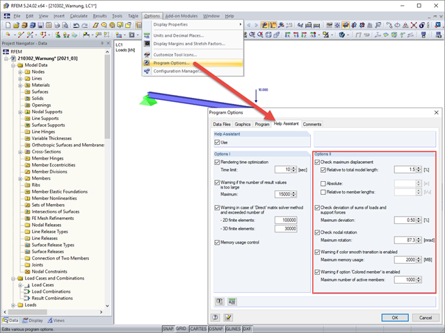
Under Options II in the Help Assistant tab of the program options, you can define the limit values for warning messages that appear after a successful calculation.
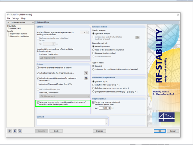
A calculation break‑off due to an unstable system can have different reasons. On one hand, it can indicate a "real" instability due to overloading of the system; on the other hand, the error message can result from inaccuracies in the model.
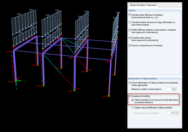
If the calculation of a member model according to the second-order analysis is terminated with an error message, this instability is often caused by failed tension members: As soon as compressive forces appear in a tension member during a calculation step, this member is no longer considered in the following iterations. Thus, the model can become unstable.
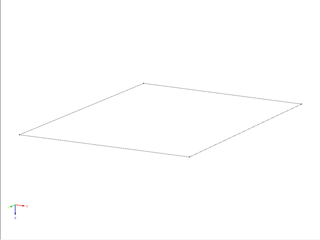
This example describes a definition of a planar surface by four nodes that have been imported and seem to lie in a common plane. In reality, they are not exactly in one plane due to (for example) a previous modeling error of a few millimeters. When trying to create a planar surface, the error message "Error in the surface definition! The nodes do not lie in a common plane." appears.
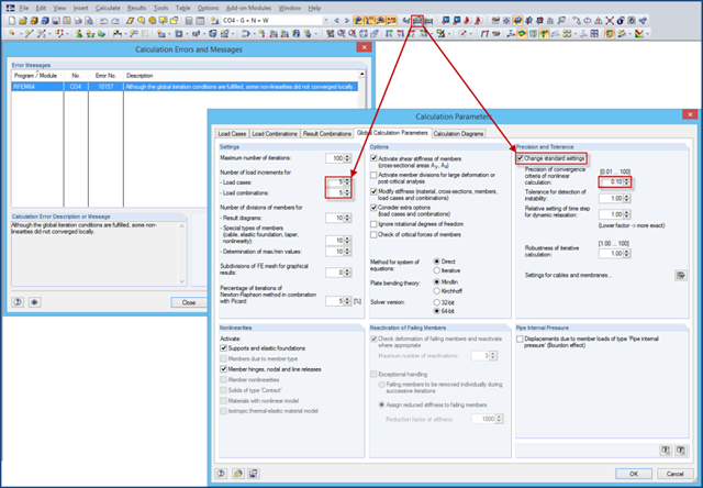
If nonlinearities are used in a model (for example, contact solids), an error message may appear at the end of the calculation due to the locally unfulfilled convergence criteria. The reason for this is that the convergence of the global iteration conditions governs in the calculation.
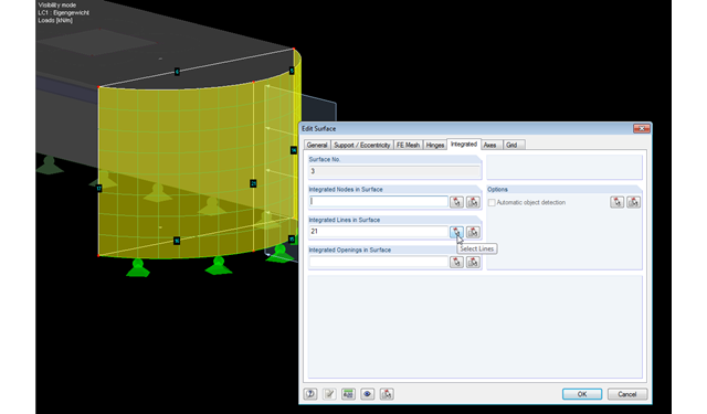
RFEM facilitates modeling by the automatic integration of objects into surfaces. However, it is impossible to integrate the objects automatically in the case of curved surfaces. For manual integration, select the relevant surfaces and click the "Edit Surfaces" option in the shortcut menu; then, in the "Integrated" tab, you can integrate the relevant objects using the "Select" function. This way, you can avoid error messages caused by non‑integrated objects when starting the calculation.
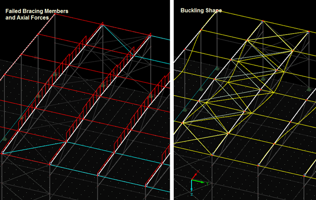
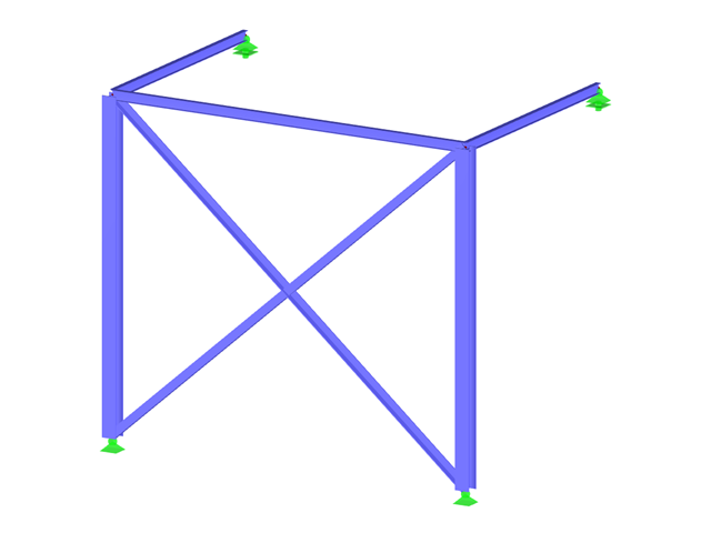
The previous post on this topic describes instabilities that may occur when using tension members. The example shown refers primarily to wall stiffening. Now, instability error messages can also refer to nodes within the range of supports. Truss girders and support trusses are especially susceptible to this. What causes the instability here?
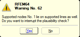
Shoring braces usually obtain the "tension member" type. There are a few specifics to note because in the case of uniform, symmetrical structures and solely vertical loads, an error message often appears as follows: "The model is unstable in node No. 20. Free movement around Y-direction."
You can define nonlinear supports in RFEM and RSTAB. In RFEM, these are represented by nodal, line, and surface supports. Many customers contact us because of nonlinearities that are apparently not acting as desired. For example, there is a failing line support in a model. Since the structure is statically determined as supported, a linear nodal support is usually added. If the nodal support rests at the start or the end of a nonlinearly supported line, there is no clear definition of the degrees of freedom, so the nonlinearity cannot be considered properly. In this case, RFEM displays a warning message.