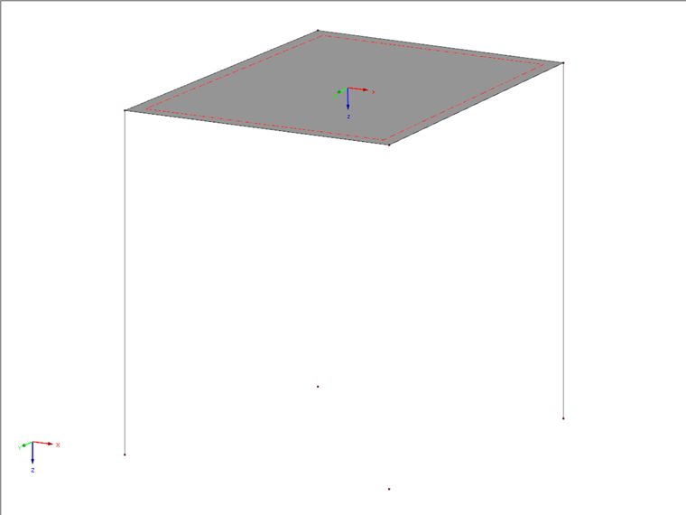
In order to have all four nodes in one plane, one node must be moved a small distance in a certain direction.
The following steps have proven to be effective:
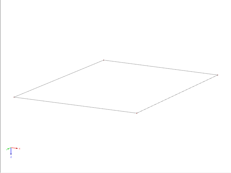
- Project the four nodes as a copy into any plane
- Draw diagonal guidelines A and B
In the example, the Diagonal Guideline A from Node 3 to Node 2 lies above the other Diagonal Line B, from Node 1 to Node 4.
- Draw a triangular auxiliary surface between Nodes 2 and 3 and the projected Node 7 (under Node 3). See Image 02.
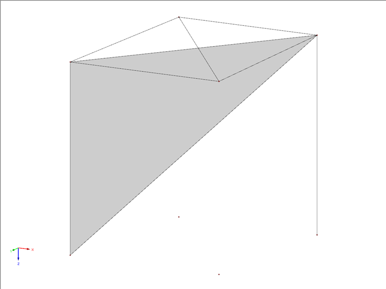
The auxiliary Diagonal B now intersects the triangular surface. After using the "Connect Lines or Members" function, a new Node 9 is created here.
- Delete the triangular auxiliary surface as well as the auxiliary diagonal A and the divided auxiliary Diagonal B.
- Draw a new line from Node 3 to Node 9.
- Extend this line at its end by a length high enough to intersect the vertical Guideline 8.
- Use the "Connect Lines or Members" function so that Node 10 is created under Node 2 on Guideline 8.
- Move Node 2 to Node 10 so that both merge into Node 10.
Node 10 is now the fourth node within the common plane of Nodes 1, 3, and 4. This allows you to draw a planar quadrilateral surface. See Image 03.