11 Results
View Results:
Sort by:

If you want to consider guide objects in the overall view (F8 key or double-click on the mouse wheel) or, for example, in a particular direction of the views, you can enable this option in the settings of the particular guide objects (guidelines, background layers, line grids).
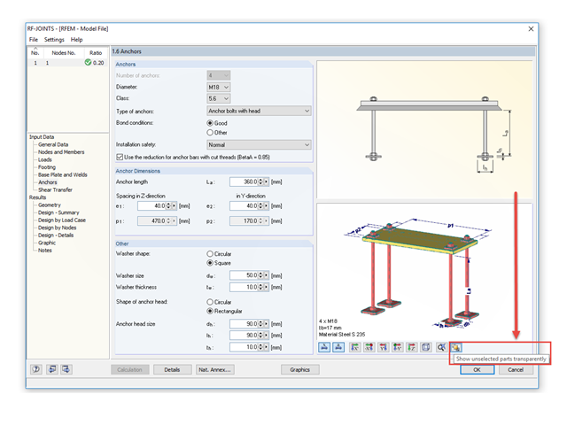
The RF‑/JOINTS add‑on modules are equipped with a graphical window that shows all the structural components of the connection. There, you can use the mouse functions known from RFEM and RSTAB to zoom, move, or rotate the view.

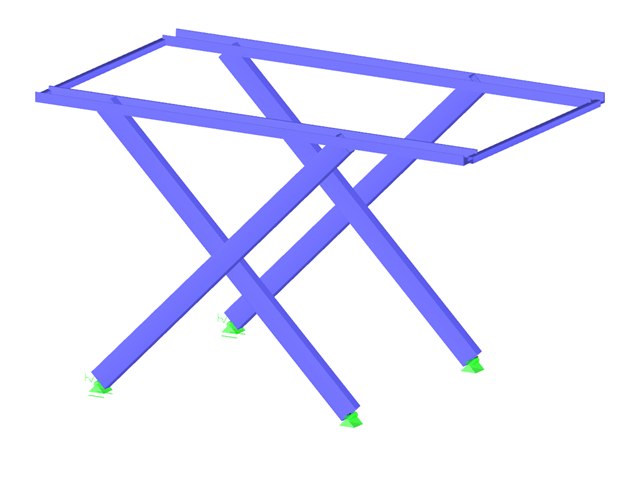
For a quick overview of the cross‑sections used, you can show the members in color sorted by cross‑section. Use the right mouse button in the work window to select "Colors in Graphics According to" → "Cross -Sections" from the shortcut menu. In the current program versions, you can use a panel with an editable color scale for this.
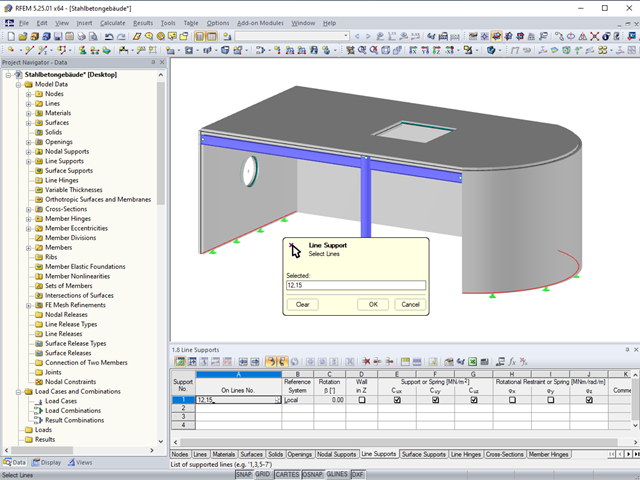
In the tables of RFEM 5 and RSTAB 8, you can select the list of objects graphically by using the mouse.
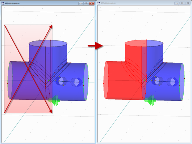
If you draw a window with your mouse from left to right, all completely included objects are selected.
It is necessary to design some structures in different configurations. It may be that an aerial work platform must be analyzed in its position on the ground as well as in the middle and in the extended position. Since such tasks require the creation of several models, which are almost identical, updating all the models with just one mouse click is a considerable relief.
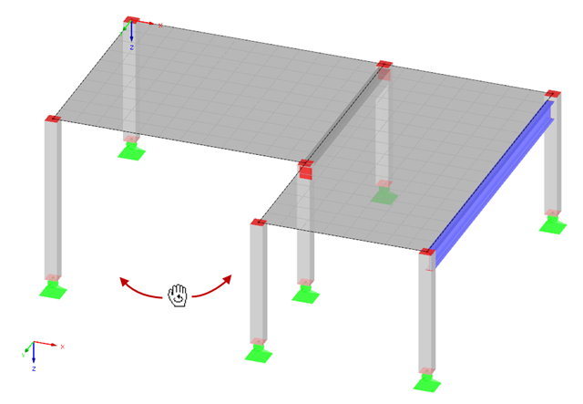
Rotating in the work window is one of the most important functions allowing you to enter a model graphically in RFEM or RSTAB.
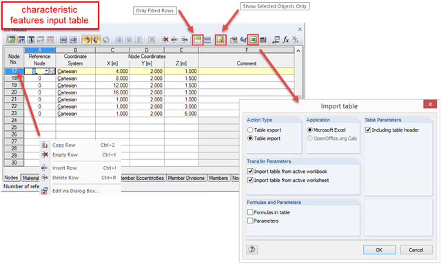
RFEM and RSTAB are programs where graphical input prevails. All data can be entered using dialog boxes, and the structure of the Project Navigator is optimized for input using the mouse. Nevertheless, you can always speed up the tabular input to reach your goal immediately.
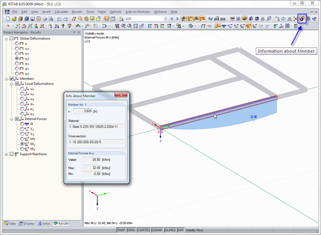
The "Info About Member" feature is available in RFEM and RSTAB. allows you to quickly read the member properties and results in a graphic. When you move the mouse over a member, the information about the member is displayed in the corresponding window.
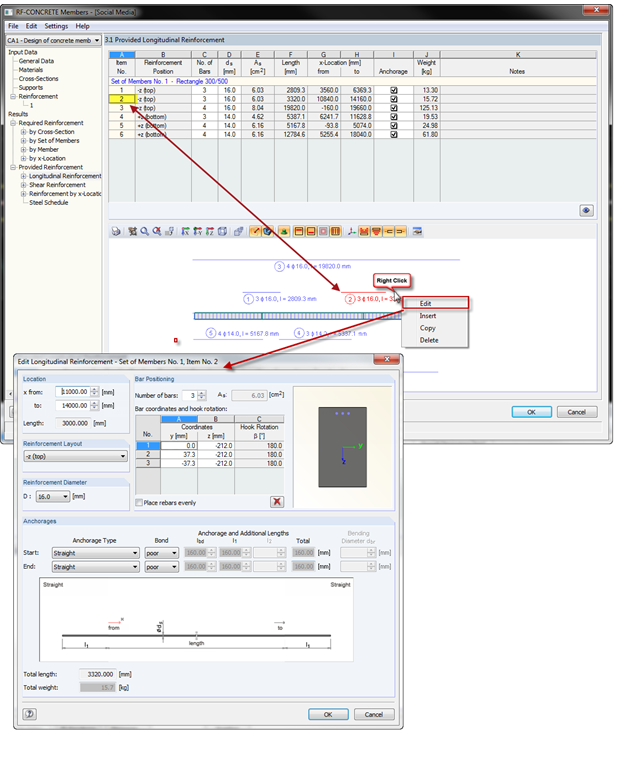
With the introduction of OSG graphics for the representation of design reinforcement in RF‑CONCRETE Members and CONCRETE, you can also select the reinforcement position directly in the graphic. Right-click the mouse to open the context menu where you can edit, copy, or delete the selected reinforcement position.
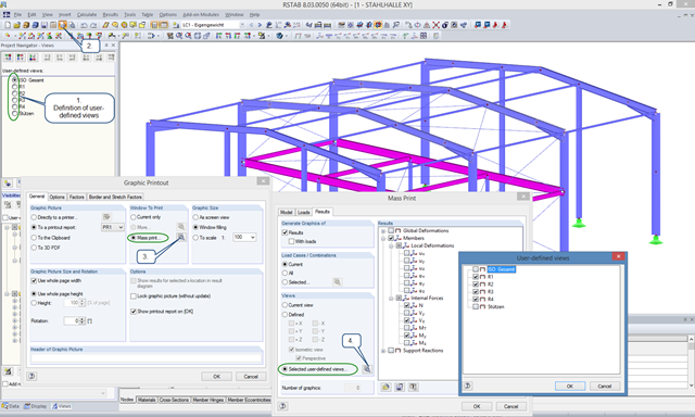
User-defined views are a very useful tool for effective modeling, as the previously selected and adapted objects appear directly with a click of the mouse. These objects can also be used easily to create informative and clearly arranged result graphics. With just a few clicks, you can create all result graphics at once using the mass print function.