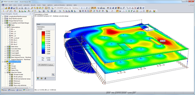
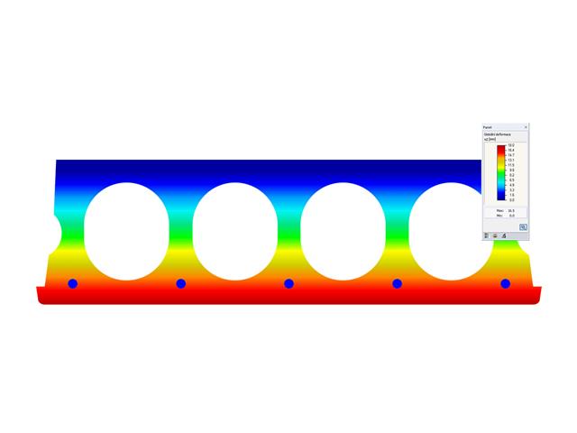
After the calculation, the module shows clearly arranged tables listing the results of the nonlinear calculation. All intermediate values are included in a comprehensible manner. Graphical representation of design ratios, deformations, concrete and reinforcing steel stresses, crack widths, crack depths, and crack spacing in RFEM facilitates a quick overview of critical or cracked areas.
Error messages or remarks concerning the calculation help you find design problems. Since the design results are displayed by surface or by point including all intermediate results, you can retrace all details of the calculation.
Due to the optional export of input or result tables to MS Excel, the data remain available for further use in other programs. The complete integration of results in the RFEM printout report guarantees verifiable structural design.
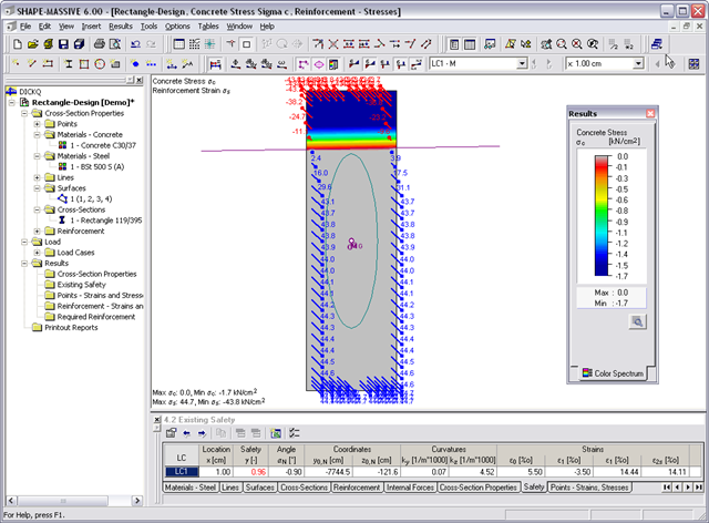
- Stresses σ and strains ε of concrete and reinforcement without considering concrete tensile strength (state II)
- Ultimate limit state design (existing safety) or design of defined internal forces
- Location of the neutral axis α0, y0,N, z0,N
- Curvatures ky, kz
- strain in the zero point ε0 and governing strains at the compression edge ε1 and at the tension edge ε2
- Governing steel strain ε2s
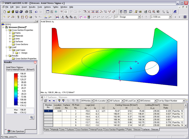
- Normal stresses σx due to axial force and bending
- Shear stresses τ due to shear force and torsion
- Equivalent stresses σv compared to limit stress
- Stress ratios related to equivalent stresses
- Normal stress σx due to unit axial force N
- Shear stress τ due to unit shear forces Vy, Vz, Vu, Vv
- Normal stress σx due to unit momentsMy, Mz, Mu, Mv
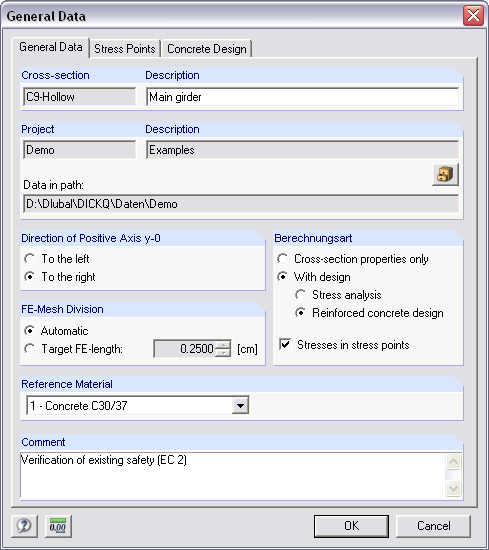
It is possible to freely model a cross-section using surfaces limited by polygonal lines, including openings and point areas (reinforcements). Alternatively, you can use the DXF interface to import the geometry. An extensive material library facilitates the modeling of composite cross-sections.
Definition of limit diameters and priorities allows for a curtailment of reinforcements. In addition, you can consider the respective concrete covers and prestresses.
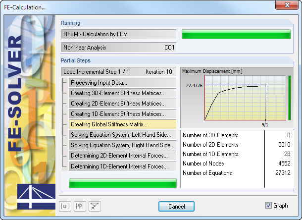
- Iterative nonlinear calculation of deformations for beam and plate structures consisting of reinforced concrete by determining the respective element stiffness subjected to the defined loads
- Deformation analyses of cracked reinforced concrete surfaces (state II)
- General nonlinear stability analysis of compression members made of reinforced concrete; for example, according to EN 1992-1-1, 5.8.6
- Tension stiffening of concrete applied between cracks
- Numerous National Annexes available for the design according to Eurocode 2 (EN 1992-1-1:2004 + A1:2014, see EC2 for RFEM)
- Optional consideration of long-term influences such as creep or shrinkage
- Nonlinear calculation of stresses in reinforcing steel and concrete
- Nonlinear calculation of crack widths
- Flexibility due to detailed setting options for basis and extent of calculations
- Graphical representation of results integrated in RFEM; for example, deformation or sag of a flat slab made of reinforced concrete
- Numerical results clearly arranged in tables and graphical display of the results in the model
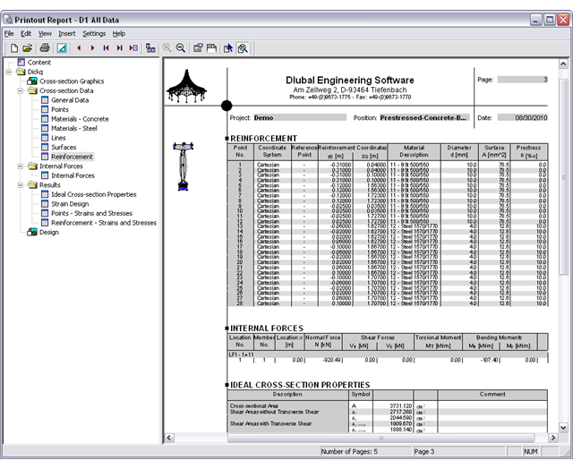
- Complete integration of results in the RFEM printout report
All results can be evaluated and visualized in an appealing numerical and graphical form. Selection functions facilitate the targeted evaluation.
The printout report corresponds to the high standards of RFEM and -rstab RSTAB. Modifications are updated automatically. Furthermore, you can print the reduced report in a short form, including all relevant data and a user-defined cross-section graphic.
RF-CONCRETE Surfaces:
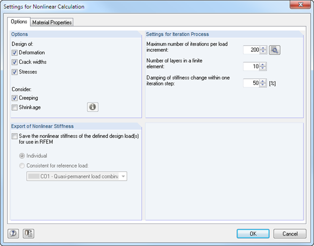
The nonlinear deformation analysis is performed by an iterative process considering the stiffness in cracked and non-cracked sections. The nonlinear reinforced concrete modeling requires definition of material properties varying across the surface thickness. Therefore, a finite element is divided into a certain number of steel and concrete layers in order to determine the cross-section depth.
The mean steel strengths used in the calculation are based on the 'Probabilistic Model Code' published by the JCSS technical committee. It is up to the user whether the steel strength is applied up to the ultimate tensile strength (increasing branch in the plastic area). Regarding material properties, it is possible to control the stress-strain diagram of the compressive and tensile strength. For the concrete compressive strength, you can select a parabolic or a parabolic-rectangular stress-strain diagram. On the tension side of the concrete, it is possible to deactivate the tensile strength as well as to apply a linear-elastic diagram, a diagram according to the CEB-FIB model code 90:1993, and concrete residual tensile strength considering the tension stiffening between the cracks.
Furthermore, you can specify which result values should be displayed after the nonlinear calculation at the serviceability limit state:
- Deformations (global, local based on non-/deformed system)
- Crack widths, depths, and spacing of the top and bottom sides in principal directions I and II
- Stresses of the concrete (stress and strain in principal direction I and II) and of the reinforcement (strain, area, profile, cover, and direction in each reinforcement direction)
RF-CONCRETE Members:
The nonlinear deformation analysis of beam structures is performed by an iterative process considering the stiffness in cracked and non-cracked sections. The material properties of concrete and reinforcing steel used in the nonlinear calculation are selected according to a limit state. The contribution of the concrete tensile strength between the cracks (tension stiffening) can be applied either by means of a modified stress-strain diagram of the reinforcing steel, or by applying a residual concrete tensile strength.
- Cross-section modeling using surfaces, openings, and point areas (reinforcements) limited by polygons
- Automatic or individual arrangement of stress points
- Extensible library of concrete, steel, and reinforcing steel materials
- Cross-section properties of reinforced concrete and composite cross-sections
- Stress analysis with yield hypothesis according to von Mises and Tresca
- Reinforced concrete design according to:
-
 DIN 1045-1:2008-08
 -
DIN 1045:1988-07
-
 ÖNORM B 4700: 2001-06-01
 -
 EN 1992-1-1:2004
-
- For the design according to EN 1992-1-1:2004, the following National Annexes are available:
-
DIN EN 1992-1-1/NA:2013-04 (Germany)
-
 NEN-EN 1992-1-1/NA:2011-11 (Netherlands)
 -
 CSN EN 1992-1-1/NA:2006-11 (Czech Republic)
 -
ÖNORM B 1992-1-1:2011-12 (Austria)
-
 UNE EN 1992-1-1/NA:2010-11 (Spain)
 -
 EN 1992-1-1 DK NA:2007-11 (Denmark)
 -
 SIST EN 1992-1-1:2005/A101:2006 (Slovenia)
 -
 NF EN 1992-1-1/NA:2007-03 (France)
 -
 STN EN 1992-1-1/NA:2008-06 (Slovakia)
 -
 SFS EN 1992-1-1/NA:2007-10 (Finland)
 -
 BS EN 1992-1-1:2004 (United Kingdom)
 -
 SS EN 1992-1-1/NA:2008-06 (Singapore)
 -
 NP EN 1992-1-1/NA:2010-02 (Portugal)
 -
 UNI EN 1992-1-1/NA:2007-07 (Italy)
 -
 SS EN 1992-1-1/NA:2008 (Sweden)
 -
 PN EN 1992-1-1/NA:2008-04 (Poland)
 -
 NBN EN 1992-1-1 ANB:2010 (Belgium)
 -
 NA to CYS EN 1992-1-1:2004/NA:2009 (Cyprus)
 -
 BDS EN 1992-1-1:2005/NA:2011 (Bulgaria)
 -
 LST EN 1992-1-1:2005/NA:2011 (Lithuania)
 -
 SR EN 1992-1-1:2004/NA:2008 (Romania)
-
- In addition to the National Annexes (NA) listed above, you can also define a specific NA, applying user‑defined limit values and parameters.
- Reinforced concrete design for stress-strain distribution, available safety, or direct design
- Results of reinforcement list and total reinforcement area
- Printout report with option to print a short form
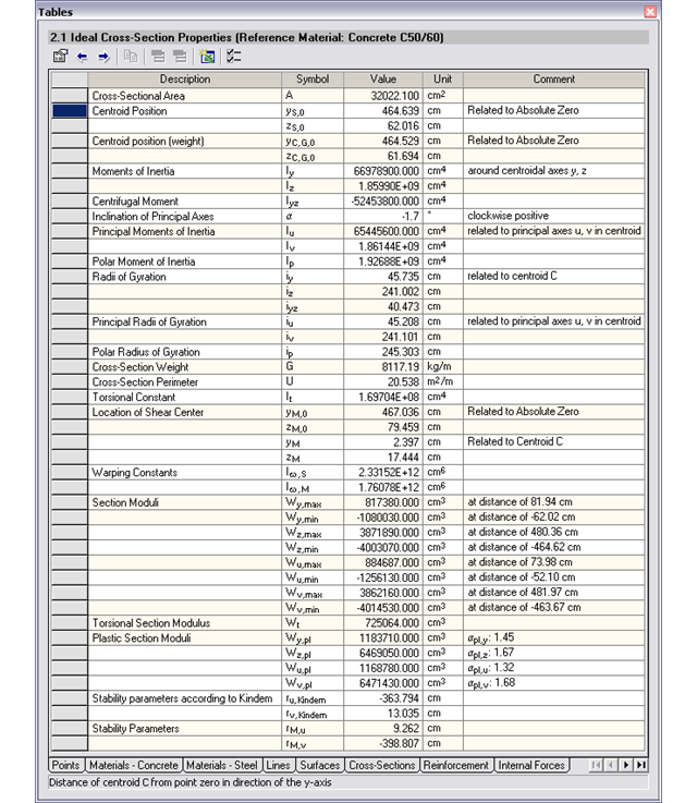
- Cross-sectional area A
- Shear areas Ay und Az with or without transversal shear
- Centroid position yS, zS
- moments of area 2 degrees Iy, Iz, Iyz, Iu, Iv, Ip
- Inclination of principal axes α
- Radii of gyration iy, iz, iyz, iu, iv, ip
- Torsional constant J
- Cross-section weight G and cross-section perimeter U
- Location of the shear center yM, zM
- Warping constants Iω,S, Iω,M
- Max/min cross-section moduli Sy, Sz, Su, Sv und St
- Plastic cross-section moduli Zy,pl, Zz,pl, Zu,pl, Zv,pl
- Stress function according to Prandtl φ
- Derivation of φ with respect to y and z
- Warping ω
The results of warping torsion analysis are displayed in RF-/STEEL AISC and RF-/STEEL EC3 in the usual way. Among other results, the corresponding result windows include the critical warping and torsional values, internal forces, and design summary.
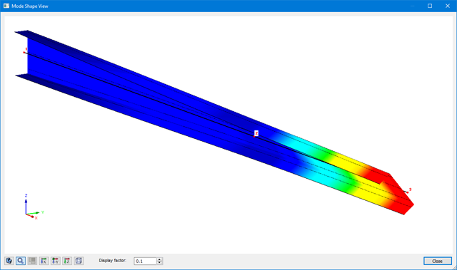
The graphical display of mode shapes (incl. warping) enables a realistic assessment of buckling behavior.