
In the RFEM add-on Surface Concrete Design allows you to perform the fire design according to the simplified table method (EN 1992-1-2, Chapter 5.4.2 and Table 5.8 and 5.9) for walls and ceilings made of reinforced concrete.

The Concrete Design add-on provides you with the option to perform the simplified fire resistance design according to EN 1992‑1‑2 for columns (Section 5.3.2) and beams (Section 5.6).
The following design checks are available for the simplified fire resistance design:
- Columns: Minimum cross-sectional dimensions for rectangular and circular sections according to Table 5.2a as well as Equation 5.7 for calculating time of fire exposure
- Beams: Minimum dimensions and center distances according to Table 5.5 and Table 5.6
You can determine the internal forces for the fire resistance design according to two methods.
- 1 Here, the internal forces of the accidental design situation are included directly into the design.
- 2 The internal forces of the design at normal temperature are reduced by the factor Eta,fi (ηfi), then used in the fire resistance design.
Furthermore, it is possible to modify the axis distance according to Eq. 5.5.

The Steel Joints add-on provides you with the option to connect circular hollow sections using welds.
It is possible to connect the circular sections to each other or to planar structural components. The fillets of standard and thin-walled sections can also be connected with a weld.
Go to Explanatory Video
With the Concrete Design add-on, you can perform the fatigue design of members and surfaces according to EN 1992‑1‑1, Chapter 6.8.
For the fatigue design, you can optionally select two methods or design levels in the design configurations:
- Design Level 1: Simplified design according to 6.8.6 and 6.8.7(2): The simplified design is performed for frequent action combinations according to EN 1992‑1‑1, Chapter 6.8.6 (2), and EN 1990, Eq. (6.15b) with the traffic loads relevant in the serviceability state. A maximum stress range according to 6.8.6 is designed for the reinforcing steel. The concrete compressive stress is determined by means of the upper and lower allowable stress according to 6.8.7(2).
- Design Level 2: Design of damage equivalent stress acc. to 6.8.5 and 6.8.7(1) (simplified fatigue design): The design using damage equivalent stress ranges is performed for the fatigue combination according to EN 1992‑1‑1, Chapter 6.8.3, Eq. (6.69) with the specifically defined cyclic action Qfat.

The Concrete Design add-on allows you to perform the seismic design of reinforced concrete members according to EC 8. This includes, among other things, the following functionalities:
- Seismic design configurations
- Differentiation of the ductility classes DCL, DCM, DCH
- Option to transfer the behavior factor from a dynamic analysis
- Check of the limit value for the behavior factor
- Capacity design checks of "Strong column - weak beam"
- Detailing and particular rules for curvature ductility factor
- Detailing and particular rules for local ductility

In the Steel Joints add-on, you can classify the joint stiffness.
In addition to the initial stiffness, the table also shows the limit values for hinged and rigid connections for the selected internal forces N, My, and/or Mz. The resulting classification is then displayed in tables as "hinged", "semi-rigid", or "rigid".
Go to Explanatory Video
In the "Steel Joints" add-on, you can consider preloaded bolts in all components during the calculation. You can easily activate the preloading using the check box in the bolt parameters, and it has an impact on the stress-strain analysis as well as the stiffness analysis.
Preloaded bolts are special bolts used in steel structures to generate a high clamping force between the connected structural components. This clamping force causes friction between the structural components, which allows for the transfer of forces.
Functionality
Preloaded bolts are tightened with a certain torque, causing them to stretch and generate a tensile force. This tensile force is transferred to the connected components and leads to a high clamping force. The clamping force prevents the connection from loosening and ensures safe force transmission.
Advantages
- High load-bearing capacity: Preloaded bolts can transfer large forces.
- Low deformation: They minimize the deformation of the connection.
- Fatigue strength: They are resistant to fatigue.
- Easy assembly: They are relatively easy to assemble and disassemble.
Analysis and Design
The calculation of preloaded bolts is performed in RFEM using the FE analysis model generated by the "Steel Joints" add-on. It takes into account the clamping force, friction between structural components, shear strength of bolts, and load-bearing capacity of the structural components. The design is carried out according to DIN EN 1993‑1‑8 (Eurocode 3) or the US standard ANSI/AISC 360‑16. You can save the created analysis model, including the results, and use it as an independent RFEM model.

The Concrete Design add-on allows you to design fiber-reinforced concrete components according to the guideline "DAfStb Steel Fiber-Reinforced Concrete".
You can use this option for the design according to EN 1992‑1‑1. The design according to the DAfStb guideline is carried out once the concrete of the "Fiber Concrete" type has been assigned to the reinforced structural component.
Go to Explanatory Video
In the "Shear Reinforcement" tab, you can select the option "Cross-ties over free rebars with active selection in graphic". It allows you to arrange additional cross-ties on free rebars of the longitudinal reinforcement.
You can activate or deactivate the position of the cross-ties in the Info Graphic. The cross-ties are applied for the ultimate limit state design and the structural design checks. They are available for the design according to EN 1992‑1‑1.
Go to Explanatory Video
The initial stiffness Sj,ini is a crucial parameter for evaluating whether a connection can be characterized as rigid, semi-rigid, or pinned.
In the "Steel Joints" add-on, you can calculate the initial stiffness Sj,ini according to Eurocode (EN 1993‑1‑8, Section 5.2.2) and AISC (AISC 360-16, Cl. E3.4) with regard to the internal forces N, My, and/or Mz.
The optional automatic transfer of initial stiffnesses allows for a directly transfer as member hinge stiffnesses in RFEM. The entire structure is then recalculated and the resulting internal forces are automatically adopted as loads in the analysis and design of the connection models.
This automated iteration process eliminates the need for manual export and import of data, reducing the amount of work and minimizing potential sources of error.
Explanatory Video: Calculation of Initial Stiffness Sj,ini
In the Steel Joint add-on, you can design the connections of members with composite cross-sections. Furthermore, you can perform joint design checks for almost all thin-walled cross-sections in the RFEM library.
Go to Explanatory Video
In the Steel Joints add-on, you can design connections according to the American standard ANSI/AISC 360‑16. The following design procedures are integrated:
- Load and Resistance Factor Design (LRFD)
- Allowable Stress Design (ASD)

The new steel sections according to the latest CISC Handbook (12th edition) are available in RFEM 6. The sections are listed in the Standardized library. In the filter, select “Canada” for the region and “CISC 12” for the standard. Alternatively, the section name can be directly entered in the search box located at the bottom of the dialog box.

Do you work with the structural components consisting of slabs? In that case, you have to perform the shear force design with the requirements of punching shear design, for example, according to 6.4, EN 1992‑1‑1. In addition to floor slabs, you can also design foundation slabs in this way.
In the Ultimate Configuration for concrete design, you can define the punching design parameters for the selected nodes.

The Aluminum Design add-on provides you with further options. Here you can also design general cross-sections that are not predefined in the cross-section library. For example, create a cross-section in the RSECTION program and then import it into RFEM/RSTAB. Depending on the design standard used, you can select from various design formats. This includes, for example, the equivalent stress analysis.
With a license for RSECTION and Effective Sections, you can also perform the design checks while taking into account the effective cross-section properties according to EN 1993‑1‑5.

You know for sure that when connecting tension-loaded components with bolted connections, you need to consider the cross-section reduction due to the bolt holes in the ultimate limit state design. The structural analysis programs also have a solution for this. In the Aluminum Design add-on, you can enter a member local section reduction for this. Enter the reduction of the cross-section as an absolute value or as a percentage of the total area at all relevant locations.

Did you use the eigenvalue solver of the add-on to determine the critical load factor within the stability analysis? In this case, you can then display the governing mode shape of the object to be designed as a result.

- Calculation of deflections and comparison with the normative or manually adjusted limit values
- Consideration of a precamber for the deflection analysis
- Different limit values are possible, depending on the design situation type
- Manual Adjustment of Reference Lengths and Segmentation by Direction
- Calculation of deflections related to the initial structure or to the deformed structure
- Further detailed design checks depending on the selected design standard (for example, vibration design according to EN 1999‑1‑1, 7.2.3)
- Graphical result display integrated in RFEM/RSTAB; for example, the design ratio of a limit value, or the deformation or the sag
- Complete integration of the results into the RFEM/RSTAB printout report

The program does a lot of work for you. For example, the load or result combinations required for the serviceability limit state are generated and calculated in RFEM/RSTAB. You can select these design situations for the deflection analysis in the Aluminum Design add-on. Depending on the specified precamber and reference system, the program determines the deformation values at each location of a member. They are then compared to the limit values.
You can specify the deformation limit value individually for each structural component in Serviceability Configuration. In this case, you define the maximum deformation depending on the reference length as the allowable limit value. By defining design supports, you can segment the components. In this way, you can determine the corresponding reference length automatically for each design direction.
And that's not all. Based on the position of the assigned design supports, the program allows you to automatically determine the distinction between beams and cantilevers. The limit value is thus determined accordingly.

You can find the serviceability limit state design checks in the result tables of the Aluminum Design add-on. They are already fully integrated there. You have the option to display the design results with all the details at each location of the designed members. You can also use graphics with the result diagrams of the design ratios.
You can integrate all result tables and graphics into the global printout report of RFEM/RSTAB as a part of the aluminum design results. RFEM/RSTAB also allows you to display and document the deformations of the entire structure independently of the add-on.

Do you prefer it clear? So do we! That's why all performed design checks for the design standard are displayed for you in a clear way. You determine a design criterion for each design check. You get design details, which include the initial values, intermediate results, and final results, arranged in a structured way for each design check. You can find the calculation process with the applied formulas, standard sources, and results in great detail in an information window in the design details.
You can find the design checks displayed in tables in the Aluminum Design add-on. Moreover, you can display the distribution of the design ratios graphically. Extensive filter options are available for you both in the table as well as in the graphical output. You can thus specifically display the desired design checks by limit state or design type in the program.
When calculating the deflection limit, you have to consider certain reference lengths. You can define these reference lengths and the segments to be checked independently of each other, depending on the direction. For this, define design supports at the intermediate nodes of a member and assign them to the respective direction for the deformation analysis. Thus, the segments are created where you can define a precamber for each direction and segment.

Note that the definition of the effective lengths in the Aluminum Design add-on is an essential requirement for the stability analysis. For this, define the nodal supports and effective length factors in the input dialog box. Do you want to clearly document the nodal supports and the resulting segments with the associated effective length factors? To check the input data, it is best for you to use the graphic display in the RFEM/RSTAB work window. Thus, you can comprehend the design at any time with minimum effort.

As usual, you enter the structural system and calculate the internal forces in the programs RFEM and RSTAB. You have unlimited access to the extensive material and cross-section libraries. Did you know that you can create general cross-sections using the RSECTION program? That saves you a lot of work.
Don't be afraid of additional windows and input chaos! Aluminum Design is completely integrated into the main programs and automatically takes into account the structure and the available calculation results. You can directly assign further entries for the aluminum design, such as effective lengths, cross-section reductions, or design parameters, to the objects to be designed. You can simply and efficiently select the elements graphically using the [Select] function.
Was your design successful? Very good, now comes the relaxed part. Because the program gives you the performed design checks in a table. You can display all result details in detail here. The clearly presented design formulas ensure that you will be able to understand the results without any problems. There is no black-box effect with Dlubal Software.
The design checks are carried out at all governing locations of the members and displayed graphically as a result diagram. You can find more detailed graphics in the result output. This includes the stress distribution on the cross-section or the governing mode shape, for example.
All input and result data are part of the RFEM/RSTAB printout report. You can select the report contents and extent specifically for the individual design checks.

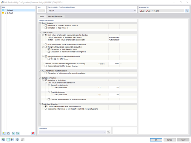
Various design parameters of the cross-sections can be adjusted in the serviceability limit state configuration. The applied cross-section condition for the deformation and crack width analysis can be controlled there.
For this, the following settings can be activated:
- Crack state calculated from associated load
- Crack state determined as an envelope from all SLS design situations
- Cracked state of cross-section - independent of load
- Deformation analyses of reinforced concrete surfaces without or with cracks (state II) by applying the approximation method (for example, deformation analysis according to ACI 318-19, 24.3.2.5 or EN 1992‑1‑1, Cl. 7.4.3 )
- Tension stiffening of concrete applied between cracks
- Optional consideration of creep and shrinkage
- Graphical representation of results integrated in RFEM, such as deformation or sag of a flat slab
- Clear numerical result display in the detail dialog box
- Complete integration of results in the RFEM printout report
Are you looking for a deformation calculation? Check the Serviceability Configuration, where it can be activated. You can also control the consideration of long-term effects (creep and shrinkage) and tension stiffening between cracks in the dialog box above. The creep coefficient and shrinkage strain are calculated using the specified input parameters, or you can define them individually.
Furthermore, you can specify the deformation limit value individually for each structural component. The max. deformation is defined as the allowable limit value. In addition, you have to specify whether you want to use the undeformed or the deformed system for the design check.

The standards already specify the approximation methods (for example, deformation calculation according to EN 1992‑1‑1, 7.4.3, or ACI 318‑19, 24.3.2.5) that you need for your deformation calculation. In this case, the so-called effective stiffnesses are calculated in the finite elements in accordance with the existing limit state with / without cracks. You can then use these effective stiffnesses to determine the deformations by means of another FEM calculation.
Consider a reinforced concrete cross-section for the calculation of the effective stiffnesses of the finite elements. Based on the internal forces determined for the serviceability limit state in RFEM, you can classify the reinforced concrete cross-section as "cracked" or "uncracked". Do you consider the effect of the concrete between the cracks? In this case, this is done by means of a distribution coefficient (for example, according to EN 1992‑1‑1, Eq. 7.19, or ACI 318‑19, 24.3.2.5). You can assume the material behavior for the concrete to be linear-elastic in the compression and tension zone until reaching the concrete tensile strength. This procedure is sufficiently precise for the serviceability limit state.
When determining the effective stiffnesses, you can take into accout the creep and shrinkage at the "cross-section level." You don't need to consider the influence of shrinkage and creep in statically indeterminate systems in this approximation method (for example, tensile forces from shrinkage strain in systems restrained on all sides are not determined and have to be considered separately). In summary, the deformation calculation is carried out in two steps:
- Calculation of effective stiffnesses of the reinforced concrete cross-section assuming linear-elastic conditions
- Calculation of the deformation using the effective stiffnesses with FEM