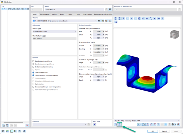
In the "Edit Section" dialog box, you can display the buckling shapes of the Finite Strip Method (FSM) as a 3D graphic.

The new steel sections according to the latest CISC Handbook (12th edition) are available in RFEM 6. The sections are listed in the Standardized library. In the filter, select “Canada” for the region and “CISC 12” for the standard. Alternatively, the section name can be directly entered in the search box located at the bottom of the dialog box.

Note that the definition of the effective lengths in the Aluminum Design add-on is an essential requirement for the stability analysis. For this, define the nodal supports and effective length factors in the input dialog box. Do you want to clearly document the nodal supports and the resulting segments with the associated effective length factors? To check the input data, it is best for you to use the graphic display in the RFEM/RSTAB work window. Thus, you can comprehend the design at any time with minimum effort.

Did you know? You can enter the soil layers that you have obtained from the subsoil expertises done in the locations into the program in the form of soil samples. Assign the explored soil materials, including their material properties, to the layers.
For the definition of the samples, you can enter the data in tables as well as in the respective editing dialog box. Furthermore, you can also specify the groundwater level in the soil samples.

When defining the input data for the modal analysis load case, you can consider a load case whose stiffnesses represent the initial position for the modal analysis. How do you do that? As shown in the image, select the "Consider initial state from" option. Now, open the "Initial State Settings" dialog box and define the type Stiffness as the initial state. In this load case, as of which is the initial state taken into account, you can consider the stiffness of the structural system when the tension members fail. The purpose of all of this: The stiffness from this load case is considered in the modal analysis. Thus, you obtain a clearly flexible system.

- The proposed connection can be applied to all selected nodes in the structure
- The location of the connection can be defined using the 'Main' tab of the Add-on dialog box
- The design is performed for all connections in the structure and after the calculation, the results on all connections can be displayed
- The table shows the results for the individual connections, each connection is designed and can be saved separately

- The design of the connection components is performed according to AISC 360 and Eurocode EN 1993‑1‑8.
- After activating the add-on, it is necessary to activate the design situations for Steel Connections in the "Load Cases and Combinations" dialog box.
- The design of the connection stability (buckling) requires the "Structure Stability" add-on.
- You can run the calculation using the table or the icon in the top bar.

Do you want to perform a stability analysis in the Steel Design add-on? Then it is absolutely necessary to define the effective lengths. To do this, define the nodal supports and effective length factors in the input dialog box. For easy documentation and a comprehensible check of the entries, you can also graphically display the nodal supports and the resulting segments with the corresponding effective length factor in the work window of RFEM/RSTAB.

Time-dependent concrete properties, such as creep and shrinkage, are very important for your calculation. You can define them directly for the material in the structural analysis program. In the input dialog box, the time course of the creep or shrinkage function is displayed to you graphically. You can easily select the modification of the applied concrete age, for example, due to a temperature treatment.
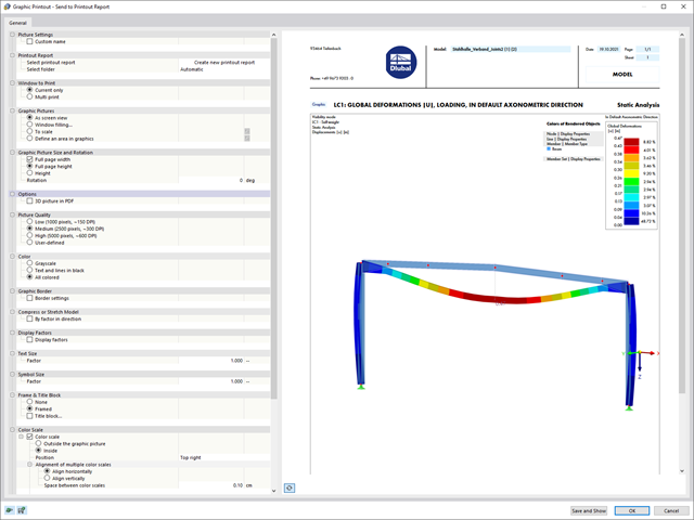
Various new options make it easier for you to print graphics in the future. Your new graphic printout dialog now includes:
- Library-controlled mass print function for all program graphics
- User-defined print area selection
- 3D function for later 3D functionalities in the final PDF
- Automatic separation of images for scale prints and the function for displaying an overview image
Both optimization methods have one thing in common. At the end of the process, they provide you with a list of model mutations from the stored data. Here you can find the details of the controlling optimization result and the associated value assignment of the optimization parameters. This list is organized in descending order. You can find the assumed best solution shown in the first line. For this, the optimization result with its determined value assignment is closest to the optimization criterion. All add-on results have a utilization < 1. Furthermore, once the analysis is completed, the program will adjust the value assignment to that of the optimal solution for the optimization parameters in the global parameter list.
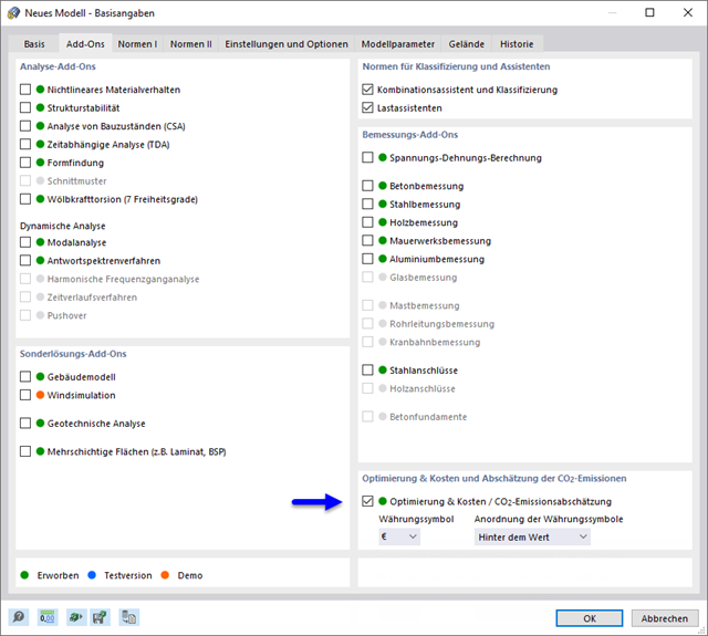
In the material dialog boxes, you can find the additional tabs "Cost Estimation" and "Estimation of CO2 Emissions". They show you the individual estimated sums of the assigned members, surfaces, and solids per unit weight, volume, and area. Furthermore, these tabs show the total cost and emission of all assigned materials. This gives you a good overview of your project.

You can display the results as usual via the Results navigator. Furthermore, the dialog box of the add-on shows you the information about the individual floors. Thus, you always have a good overview.
- Deformation analyses of reinforced concrete surfaces without or with cracks (state II) by applying the approximation method (for example, deformation analysis according to ACI 318-19, 24.3.2.5 or EN 1992‑1‑1, Cl. 7.4.3 )
- Tension stiffening of concrete applied between cracks
- Optional consideration of creep and shrinkage
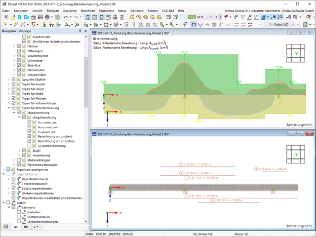
- Graphical representation of results integrated in RFEM, such as deformation or sag of a flat slab
- Clear numerical result display in the detail dialog box
- Complete integration of results in the RFEM printout report
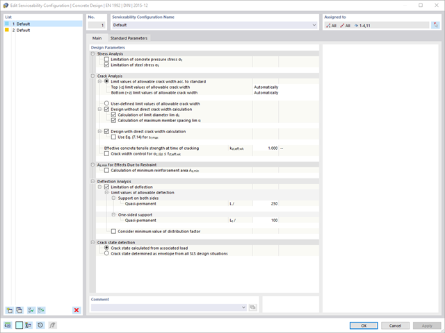
Are you looking for a deformation calculation? Check the Serviceability Configuration, where it can be activated. You can also control the consideration of long-term effects (creep and shrinkage) and tension stiffening between cracks in the dialog box above. The creep coefficient and shrinkage strain are calculated using the specified input parameters, or you can define them individually.
Furthermore, you can specify the deformation limit value individually for each structural component. The max. deformation is defined as the allowable limit value. In addition, you have to specify whether you want to use the undeformed or the deformed system for the design check.

Have you carried out the design successfully? The results of the deformation analysis are now listed in clearly arranged output tables or detailed dialog boxes with info text. The program shows you all intermediate values in a comprehensible manner. Graphical representation of design ratios and deformation in RFEM allows you for a quick overview of critical areas.
Due to the results output of the design checks with all intermediate results, you can follow the calculation to the smallest detail. The complete integration of results in the RFEM printout report ensures that you obtain verifiable structural design.

Entering soil layers for soil samples is performed in a clearly arranged dialog box. A corresponding graphical representation supports clarity and makes checking the input user-friendly.
An extensible database facilitates the selection of soil material properties. The Mohr-Coulomb model as well as a nonlinear model with stress and strain dependent stiffness are available for a realistic modeling of the soil material behavior.
You can define any number of soil samples and layers. The soil is generated from all entered samples using 3D solids. Assignment to the structure is carried out using coordinates.
The soil body is calculated according to the nonlinear iterative method. The calculated stresses and settlements are displayed graphically and in tables.

After you have completed the design, the program takes care of clearly arranged results. Thus, the program shows you the resulting maximum stresses and stress ratios sorted by section, member/surface, solid, member set, x-location, and so on. In addition to the tabular result values, the add-on shows you the corresponding cross-section graphic with stress points, stress diagram, and values as well. You can relate the design ratio to any kind of stress type. The current location is highlighted in the RFEM/RSTAB model.
In addition to the tabular evaluation, the program offers you even more. You can also graphically check the stresses and design ratios on the RFEM/RSTAB model. It is possible for you to adjust the colors and values individually.
The display of result diagrams of a member or set of members enables you a targeted evaluation. For each design location, you can open the respective dialog box to check the design-relevant section properties and stress components of any stress point. Finally, you have the option of printing the corresponding graphic, including all design details.

- You can activate or deactivate the use of torsional warping in the Add-ons tab of the model's Base Data.
- After activating the add-on, the user interface in RFEM is extended by some new entries in the navigator, tables, and dialog boxes.
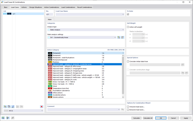
To ensure that your structures can cope with all loads, take a look at the "Load Cases and Combinations" dialog box. Here you can create and manage load cases. Furthermore, you can also generate action and load combinations as well as design situations here. You can assign the action categories of the selected standard to the individual load cases. If you have assigned several loads to an action category, they can act simultaneously or alternatively (for example, either wind from the left or wind from the right).
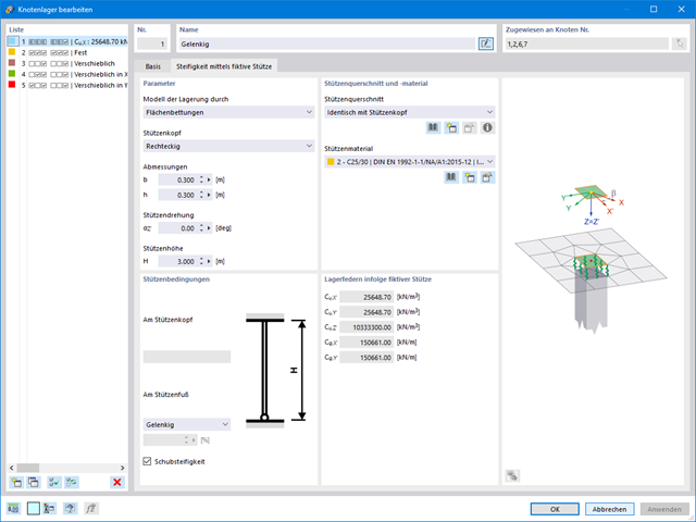
If you are working with nonlinearities, this feature is suited very well to support you. For example, you can specify nonlinearities of member end releases (yielding, tearing, slippage, and so on) and supports (including friction). Furthermore, you can use special dialog boxes to determine the spring stiffnesses of columns and walls based on the geometry specifications.
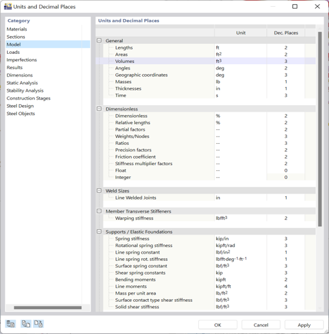
You can keep track of things with just a few clicks. A global dialog box manages the units for input data, loads, and results in RFEM or RSTAB, as well as in all add-ons.
You can save the settings and import them again later. In this way, it is possible for you to use different sections in steel and reinforced concrete structures, for example.
Go to Explanatory Video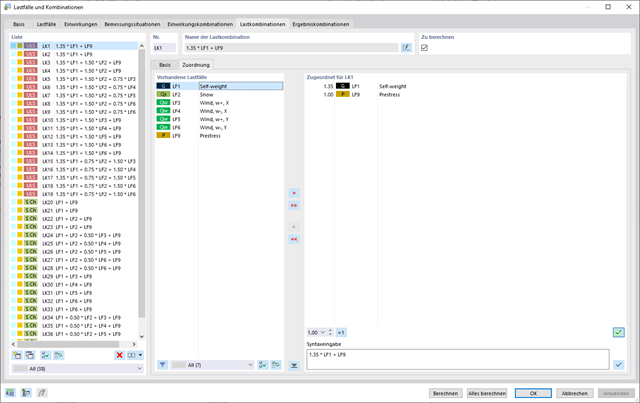
In the "Load Cases & Combinations" dialog box, you have an option to automatically generate load and result combinations as soon as you have selected the corresponding combination expressions. For example, you can also copy or add load cases in a clearly arranged window.
Furthermore, you can manage the load cases and combinations in the tables.
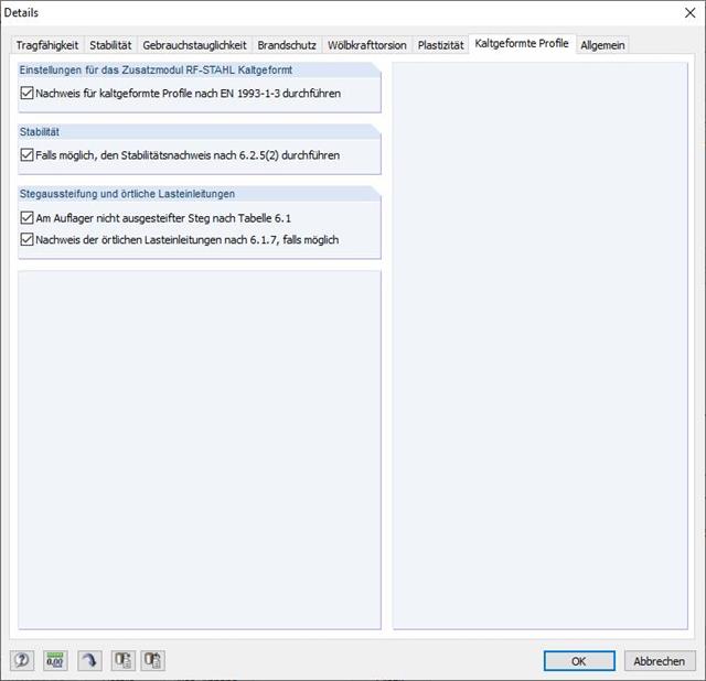
Since RF-/STEEL Cold-Formed Sections is fully integrated in RF-/STEEL EC3, the data are entered in the same way as for the usual design in this module. It is only necessary to select the design option for cold-formed cross-sections in the Details dialog box.
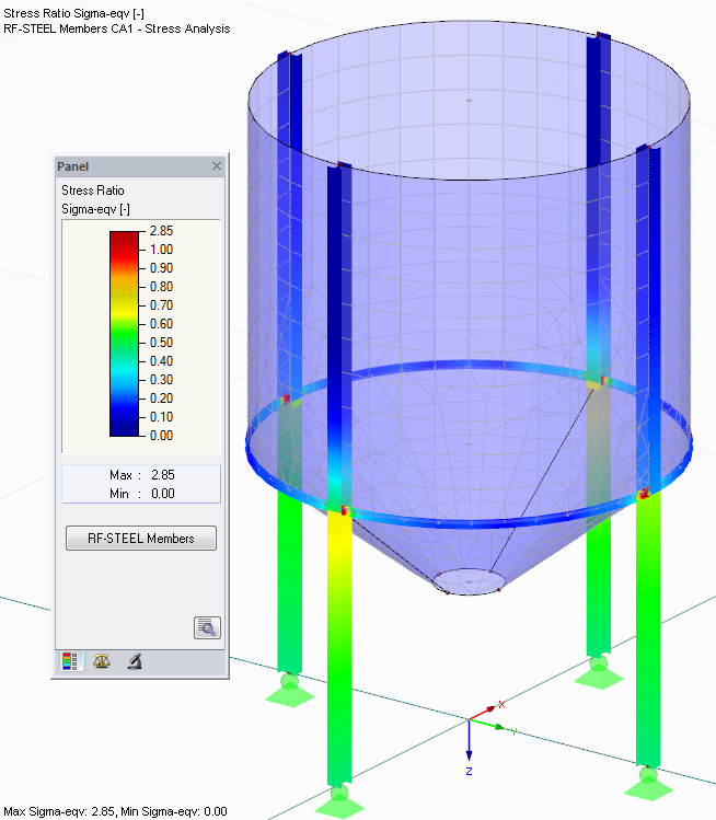
After the calculation, the maximum stresses and stress ratios are displayed sorted by sections, members/surfaces, member sets, or x-locations. In addition to the tabular result values, the corresponding cross-section graphic with stress points, stress diagram, and values is displayed as well. The design ratio can be related to any kind of stress type. The current location is highlighted in the RFEM/RSTAB model.
In addition to the result evaluation in the module, it is possible to represent the stresses and stress ratios graphically in the RFEM/RSTAB work window. It is possible to individually adjust the colors and values.
Result diagrams of a member or set of members facilitate targeted evaluation. Furthermore, you can open the respective dialog box of each design location to check the design-relevant section properties and stress components of any stress point. It is possible to print the corresponding graphic, including all design details.
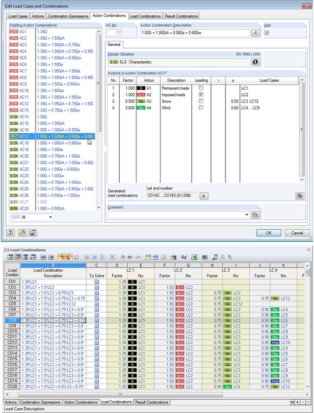
Utilize all the options of the 'Edit Load Cases and Combinations' dialog box to facilitate your work. Here you can automatically create load and result combinations after selecting the corresponding combination expressions. In this clearly arranged dialog box, you can also e.g. to copy, add, or renumber load cases.
Additionally, control the load cases and combinations in Tables 2.1 – 2.6.
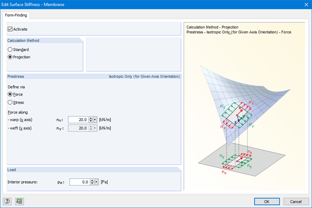
The form-finding function can be activated in the General Data dialog box, Options tab. Prestresses (or geometrical requirements for members) can be defined in the parameters for surfaces and members. The form‑finding process is performed by calculation of an RF‑FORM‑FINDING case.
Steps of the working sequence:
- Creation of a model in RFEM (surfaces, beams, cables, supports, material definition, and so on)
- Setting of required prestress for membranes and force or length/sag for members (for example, cable)
- Optional consideration of other loads for the form-finding process in special form‑finding load cases (self‑weight, pressure, steel node weight, and so on)
- Setting of loads and load combinations for further structural analyses
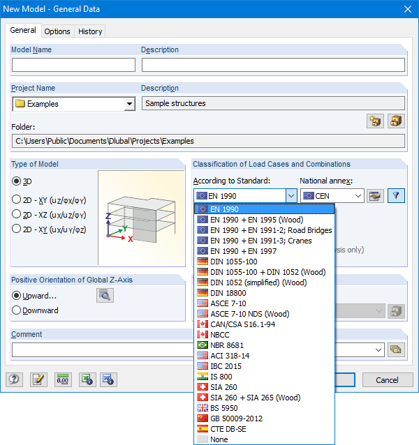
The Base Data dialog box includes a wide range of standards and the option to create combinations automatically. The following standards are available:
-
 EN 1990:2002
 -
EN 1990 + EN 1995:2004 (Timber)
-
EN 1990 + EN 1991-2; Road bridges
-
EN 1990 + EN 1991-3; Cranes
-
EN 1990 + EN 1997
-
 to DIN 1055-100:2001-03
 -
DIN 1055-100 + DIN 1052:2004-08 (timber)
-
DIN 1055-100 + DIN 18008 (Glass)
-
DIN 1052 (simplified) (timber)
-
DIN 18800:1990
-
 ASCE 7‑10
 -
ASCE 7-10 NDS (Wood)
-
ACI 318-14
-
IBC 2015
-
 CAN/CSA S 16.1-94:1994
 -
NBCC: 2005
-
 NBR 8681
 -
 IS 800:2007
 -
 SIA 260:2003
 -
SIA 260 + SIA 265:2003 (timber)
-
 BS 5950-1:2000
 -
 GB 50009-2012
 -
 CTE DB-SE
For the European standards (EC), the following National Annexes are available:
-
DIN EN 1990/NA:2009-05 (Germany)
-
 NBN EN 1990 - ANB: 2005 (Belgium)
 -
 BDS EN 1990:2003/NA:2008 (Bulgaria)
 -
 DK EN 1990/NA:2007-07 (Denmark)
 -
 SFS EN 1990/NA:2005 (Finland)
 -
 NF EN 1990/NA:2005/12 (France)
 -
 ELOT EN 1990:2009 (Greece)
 -
 UNI EN 1990/NA:2007-07 (Italy)
 -
 IS EN 1990:2002 + NA:2010 (Ireland)
 -
 LVS EN 1990:2003/NA:2010 (Latvia)
 -
 LST EN 1990/NA:2010-11 (Lithuania)
 -
 LU EN 1990/NA:2011-09 (Luxembourg)
 -
 MS EN 1990:2010 (Malaysia)
 -
 NEN EN 1990/NA:2006 (Netherlands)
 - NS EN 1990/NA:2008 (Norway)
-
 ÖNORM EN 1990:2007-02 (Austria)
 -
 NP EN 1990:2009 (Portugal)
 -
 PN EN 1990/NA:2004 (Poland)
 -
 SR EN 1990/NA:2006-10 (Romania)
 -
 SIST EN 1990: 2004/A1:2005 (Slovenia)
 -
 SS EN 1990:2008 (Singapore)
 -
 SS EN 1990/BFS 2010:28 (Sweden)
 -
 STN EN 1990/NA:2009-08 (Slovakia)
 -
UNE EN 1990 2003 (Spain)
-
 CSN EN 1990/NA:2004-03 (Czech Republic)
 -
BS EN 1990/NA:2004-12 (the United Kingdom)
-
 TKP EN 1990/NA:2011 (Belarus)
 -
 CYS EN 1990:2002 (Cyprus)
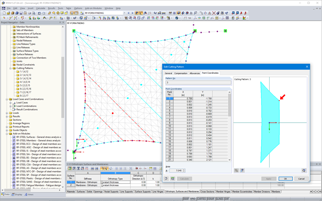
After the calculation, the "Point Coordinates" tab appears in the cutting pattern dialog box. In this tab, the result is displayed in the form of a table with coordinates and a surface in the graphical window. The coordinate table presents new flattened coordinates relative to the centroid of the cutting pattern for each mesh node. Furthermore, the cutting pattern with the coordinate system at the centroid is represented in the graphical window. When selecting a table cell, the respective node is displayed with an arrow in the graphic. In addition, the area of the cutting pattern is displayed below the node table.
Moreover, standard stress/strain results for each pattern are displayed in the RF‑CUTTING‑PATTERN load case in RFEM.
Features:
- Results in a table, including information about the cutting pattern
- Smart table relating to the graphic
- Results of flattened geometry in a DXF file
- Output of strains after flattening in order to evaluate the cutting patterns
- Results of strains after flattening for the evaluation of patterns
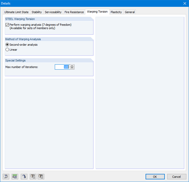
Since RF-/STEEL Warping Torsion is fully integrated in RF-/STEEL AISC and RF‑/STEEL EC3, the data are entered in the same way as for the usual design in these modules. It is only necessary to select the option "Perform warping analysis" in the Details dialog box, tab Warping Torsion (see the figure on the right). You can also define the maximum number of iterations in this dialog box.
The warping torsion analysis is performed for sets of members in RF-/STEEL AISC and RF‑/STEEL EC3. You can define boundary conditions such as nodal supports or member end releases for them.
It is also possible to specify imperfections for the nonlinear calculation.
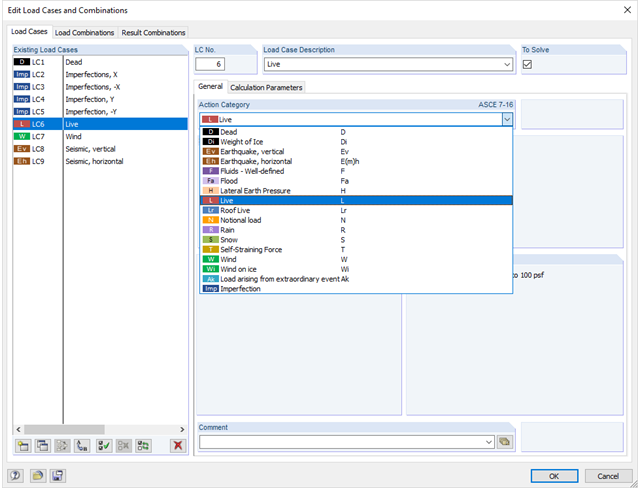
In the "Edit Load Cases and Combinations" dialog box, you can create and edit load cases as well as generate action, load, and result combinations. It is possible to assign various action types to the individual load cases in accordance with the selected standard. If several loads have been assigned to one action type, they can act simultaneously or alternatively (for example, wind from the left or right).