
The building story generator in the Building Model add-on allows you to automatically create building stories, depending on the topology of the model.

- Calculation of stationary incompressible turbulent wind flow using the SimpleFOAM solver from the OpenFOAM® software package
- Numerical scheme according to the first and second order
- Turbulence models RAS k-ω and RAS k-ε
- Consideration of surface roughness depending on model zones
- Model design via VTP, STL, OBJ, and IFC files
- Operation via bidirectional interface of RFEM or RSTAB for importing model geometries with standard-based wind loads and exporting wind load cases with probe-based printout report tables
- Intuitive model changes via drag & drop and graphical adjustment assistance
- Generation of a shrink-wrap mesh envelope around the model geometry
- Consideration of environmental objects (buildings, terrain, and so on)
- Height-dependent description of the wind load (wind speed and turbulence intensity)
- Automatic meshing depending on a selected depth of detail
- Consideration of layer meshes near the model surfaces
- Parallelized calculation with optimal utilization of all processor cores of a computer
- Graphical output of the surface results on the model surfaces (surface pressure, Cp coefficients)
- Graphical output of the flow field and vector results (pressure field, velocity field, turbulence – k-ω field, and turbulence – k-ε field, velocity vectors) on Clipper/Slicer planes
- Display of 3D wind flow via animated streamline graphics
- Definition of point and line probes
- Multilingual user interface (German, English, Czech, Spanish, French, Italian, Polish, Portuguese, Russian, and Chinese)
- Calculations of several models in one batch process
- Generator for creating rotated models to simulate different wind directions
- Optional interruption and continuation of the calculation
- Individual color panel per result graphic
- Display of diagrams with separate output of results on both sides of a surface
- Output of the dimensionless wall distance y+ in the mesh inspector details for the simplified model mesh
- Determination of the shear stress on the model surface from the flow around the model
- Calculation with an alternative convergence criterion (you can select between the residual types pressure or flow resistance in the simulation parameters)
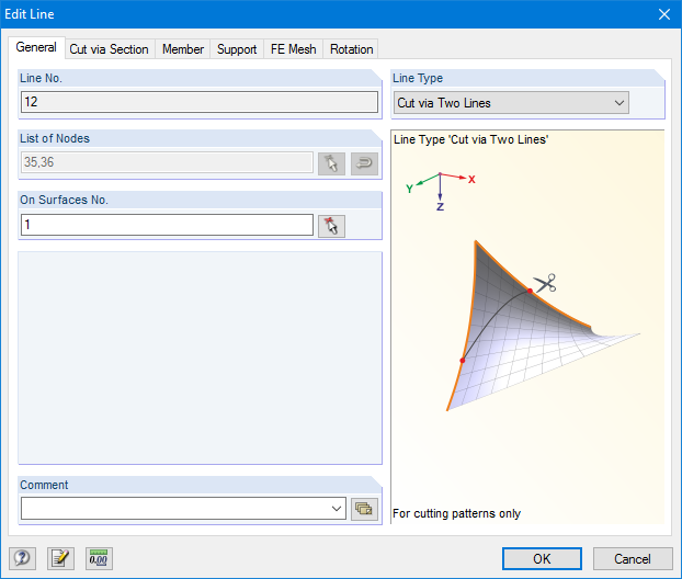
RF-CUTTING-PATTERN is activated by selecting the respective option in the Options tab in General Data of any RFEM model. After activating the add‑on module, a new object, "Cutting Patterns", is displayed under Model Data. If the membrane surface distribution for cutting in the basic position is too large, you can divide the surface by cutting lines (line types "Cut via Two Lines" or "Cut via Section") in the corresponding partial strips.
Then you can define the individual entries for each cutting pattern using the "Cutting Pattern" object. Here you can set boundary lines, compensations, and allowances.
Steps of the working sequence:
- Creation of cutting lines
- Creation of the pattern by selecting its boundary lines or using a semi‑automatic generator
- Free selection of warp and weft orientation by entering an angle
- Application of compensation values
- Optional definition of different compensations for boundary lines
- Different allowances (welding, boundary line)
- Preliminary representation of the cutting pattern in the graphic window at the side without starting the main nonlinear calculation
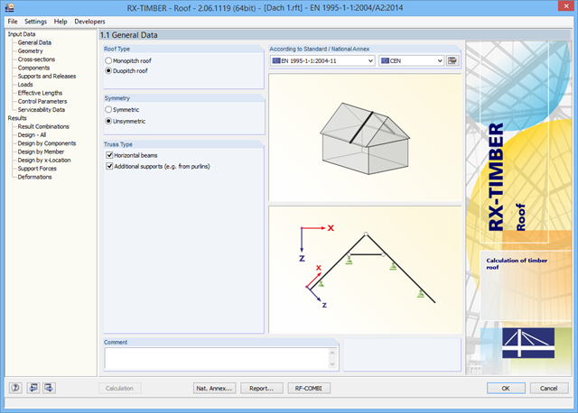
There are various options available for modeling a roof. Graphical representations facilitate the geometry input. Modifications are updated automatically.
In addition, it is possible to consider cross‑section weakening on supports. Optionally, you can define if the design of support pressure on the rafter side should be performed.
Permanent loads (for example, roof structure) can be entered using the comprehensive and extensible material library. Loads due to cantilevers and collars/ties can be entered separately. Generators integrated in RX-TIMBER Purlin allow for convenient generation of various wind and snow load cases. You can manually add any concentrated and distributed loads.
Load cases are displayed graphically and superimposed in automatically generated load combinations according to EC 5. For stability and serviceability limit state designs, you can change the data manually, for example, for example, for cantilevers (roof overhang), it is necessary to ignore the SLS.
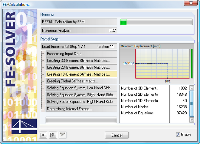
The equation solver includes an optimized FE mesh generator and supports the latest multi-core processor and 64-bit technology. It enables parallel calculations of linear load cases and load combinations using several processors without additional demands on the RAM: The stiffness matrix only has to be created once. The 64-bit technology and the enhanced RAM options allow for calculation of complex structural systems using the fast and direct equation solver.
The development of the deformation is displayed in a diagram during the calculation. This way, you can easily evaluate the convergence behavior.
There are load generators available for beam structures, creating snow loads according to ASCE/SEI 7-10. The load cases are generated depending on the roof shape. Another generator creates coating loads (ice). You can save recurring load combinations as templates.
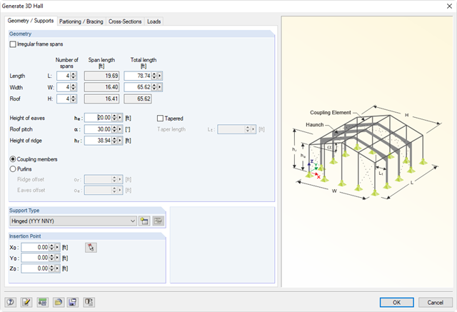
Generating tools to enter parametric models such as frames, halls, trusses, spiral stairways, arcs, or roofs. In addition, many generators allow for the creation of load cases and loading resulting from weight, snow, and wind.
- Structure generator for typical geometries with loading and combinations
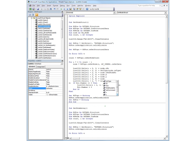
- Importing and exporting data from spreadsheet programs such as MS Excel and MS Access
- Connection to various programs compatible with COM, for example, B. CAD systems
- Customized pre- and postprocessing modules
- Processing and results of data in user-defined formats
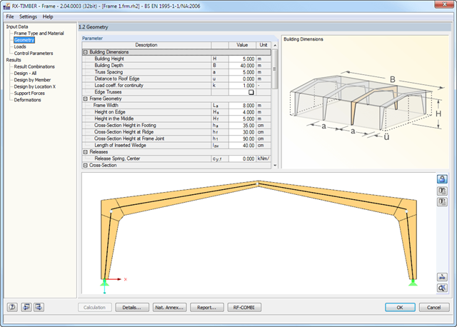
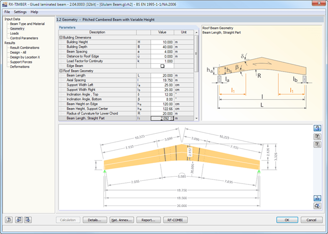
There are various options available for frame modeling. Graphical representations facilitate the geometry input. Modifications are updated automatically. Basic dimensions as well as geometrical data are entered in tables. During the input, the program checks the conditions required for the beam creation (for example, lamellas forming a curve) according to the defined standard. The most important geometry parameters are updated and displayed.
The relevant timber grade of the material can be selected from the material library. All material grades for glulam, hardwood, poplar and softwood timber specified in EN 1995-1-1 are available. Furthermore, it is possible to generate a strength class with user-defined material properties in order to extend the library. Permanent loads (for example, roof structure) can also be entered using the comprehensive and extensible material library.
Generators integrated in RX-TIMBER Purlin allow for convenient generation of various wind and snow load cases. By clicking the information buttons, the map of wind and snow zones for the relevant country is displayed. The corresponding zone can be selected with a double-click. Load cases can be checked graphically. However, you can enter load specifications manually as well. According to the generated loads, the program automatically creates combinations for the ultimate and serviceability limit states as well as for fire resistance design in the background. The generated combinations can be considered or adjusted by user-defined specifications.
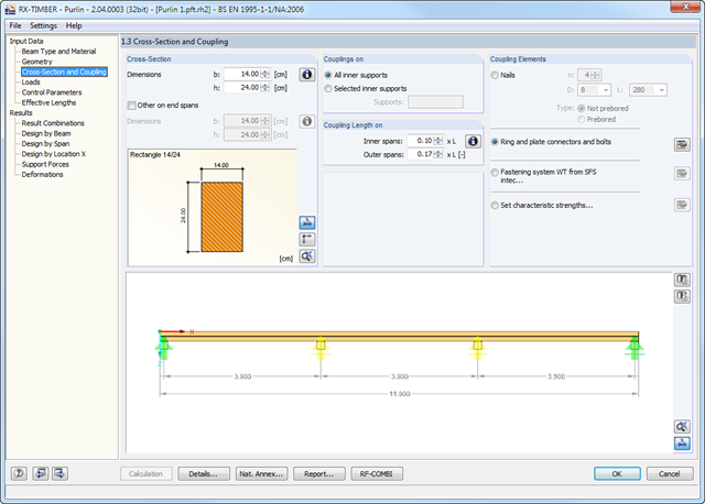
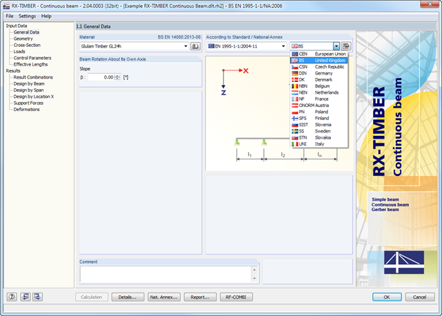
There are various options available for beam modeling. A roof type determines the exact purlin location for wind and snow generation.
Two beam types are available: continuous beam and purlin. If you select the continuous beam, it is possible to define several hinge conditions of the beam. If you select the purlin, it is not possible to modify hinge conditions. In this case, the calculation considers a double cross-section in the coupling zone. In addition, several coupling elements are available in the purlin settings:
- Nails (prebored/not prebored)
- Ring and plate connectors and bolts
- Screw connection with fastening system WT from SFS intec
- User-defined specification using characteristic strength
The relevant timber grade of the material can be selected from the material library. All material grades for glulam, hardwood and softwood timber specified in EC 5 are available. Furthermore, you have the option to generate a strength class with user-defined material properties and thus extend the library.A comprehensive and extensible material library can also be used for entering permanent loads (for example, roof structure).
Generators integrated in RX-TIMBER Purlin allow for convenient generation of various wind and snow load cases. By clicking the information buttons, the map of wind and snow zones for the relevant country is displayed. The corresponding zone can be selected with a double-click. Load cases can be checked graphically.
However, you can enter load specifications manually as well. According to the generated loads, the program automatically creates combinations for the ultimate and serviceability limit states as well as for fire resistance design in the background.
There are various options available for beam modeling. Graphical representations facilitate the geometry input. Modifications are updated automatically. Deflection of cantilevers can be set in the serviceability limit state design, independently of the deflection in the span.
In order to enter permanent loads (for example, roof structure), you can use a comprehensive and extensible material library. Generators integrated in RX-TIMBER Purlin allow for convenient generation of various wind and snow load cases.
Load cases are displayed graphically and superimposed in automatically generated load combinations according to EC 5. This way, the required input data are reduced to a minimum. However, you can enter load specifications manually as well.
There are various options available for beam modeling. Graphical representations facilitate the geometry input. Modifications are updated automatically. Deflection of cantilevers can be set in the serviceability limit state design, independently of the deflection in the span.
The relevant timber grade of the material can be selected from the material library. All material grades specified in EN 1995-1-1: 2004 (EC 5) or DIN 1052:2008-12 and the selected National Annex are available for glulam, hardwood, and softwood timber. Furthermore, it is possible to generate a strength class with user-defined material properties in order to extend the library. Permanent loads (for example, roof structure) can also be entered using the comprehensive and extensible material library.
Generators integrated in RX-TIMBER Purlin allow for convenient generation of various wind and snow load cases. Load cases are displayed graphically and superimposed in automatically generated load combinations according to EN 1990, DIN 1055-100, or DIN 1052. This way, the required input data are reduced to a minimum. However, you can enter load specifications manually as well.
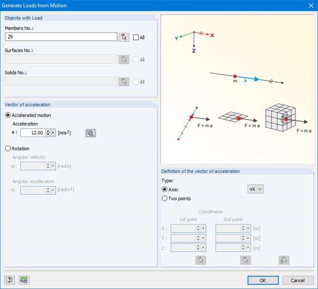
This generator creates loads as a result of an acceleration or rotation (e.g. from tower cranes), which acts on specific objects of the model.
The mass is determined from the self-weight.
More Information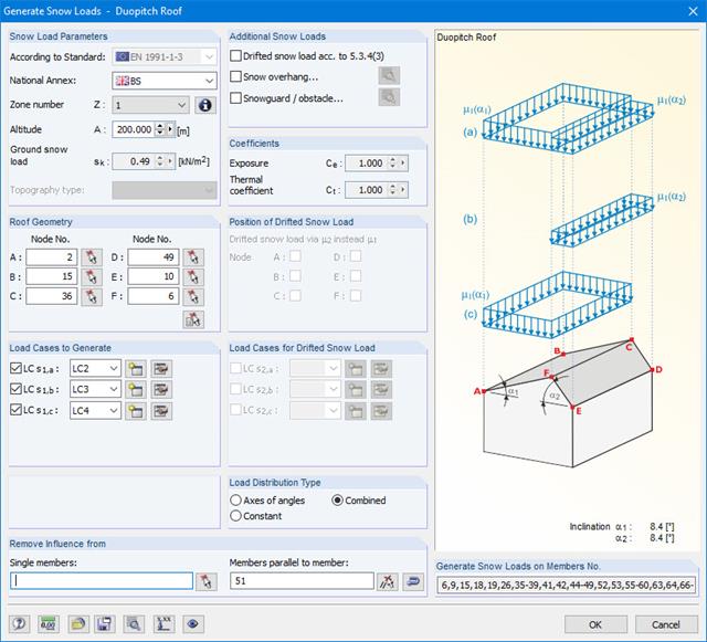
Snow loads can be generated as member loads on flat/monopitch roofs and duopitch roofs.
Additional snow loads such as drifted snow loads, snow overhangs, and snow guards can be taken into account as well.
The following standards are available:
-
 EN 1991-1-3 (incl. National Annexes)
 -
 DIN 1055-5
 -
 CTE DB-SE-AE
 -
 ASCE/SEI 7-16
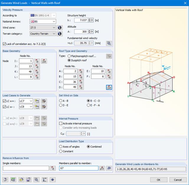
Wind loads can be automatically generated as member loads on the following structural components (optional with internal pressure for open buildings):
- Vertical walls
- Flat roofs
- Monopitch roofs
- Duopitch/troughed roofs
- Vertical walls with roof
The following standards are available:
-
EN 1991-1-3 (incl. National Annexes)
-
DIN 1055-4
-
CTE DB-SE-AE
-
ASCE/SEI 7-16
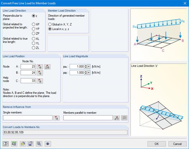
With this generator, you can e.g. for grillages, you can define free line loads (e.g. from conveyor belts) and prorate them to members.
More Information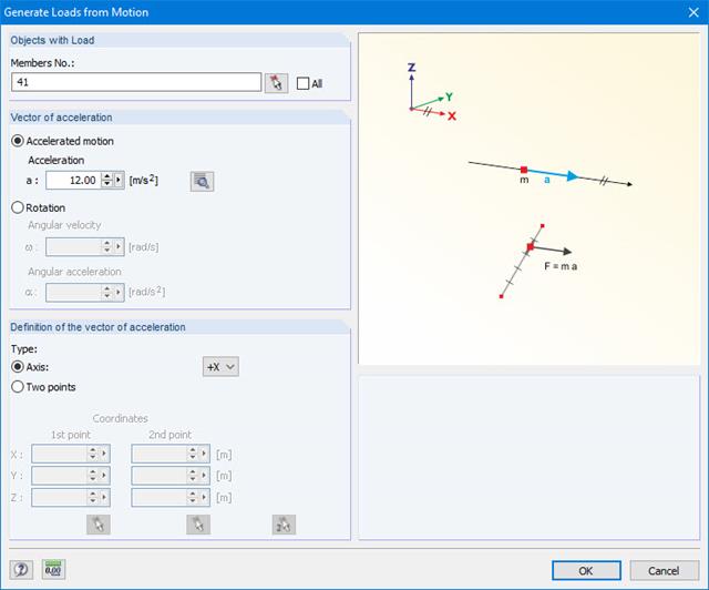
This generator creates loads as a result of an acceleration or rotation that acts on specific objects of the model.
The mass is determined from the self-weight.
More Information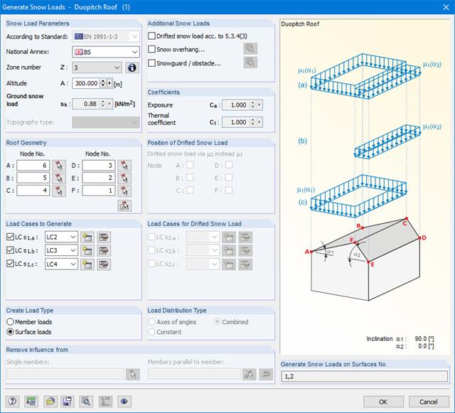
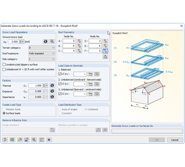
The snow load generator can generate snow loads as member loads or surface loads.
Additional snow loads such as drifted snow loads, snow overhangs, and snow guards can be taken into account as well.
The following standards are available:
-
EN 1991-1-3 (incl. National Annexes)
-
DIN 1055-5
-
CTE DB-SE-AE
-
ASCE/SEI 7-16

Wind loads can be automatically generated as member loads or area loads on the following structural components (optional with internal pressure for open buildings):
- Vertical walls
- Flat roofs
- Monopitch roofs
- Duopitch/troughed roofs
- Vertical walls with roof
The following standards are available:
-
EN 1991-1-3 (incl. National Annexes)
-
DIN 1055-4
-
CTE DB-SE-AE
-
ASCE/SEI 7-16