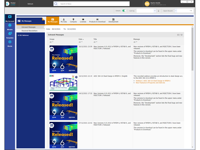
Take a look at the "My Account" category. This is where your customer data, such as address, licensed programs, and add-ons are managed. It also takes you straight to the Dlubal website. Find out about the latest news there, use online services such as "Snow Load Zones, Wind Zones and Earthquake Zones", or get helpful information from the FAQ database.
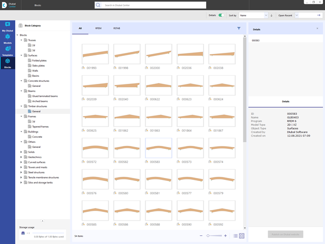
Are you looking for models for your design? Then you have come to the right place at the Dlubal Center. It contains an extensive database with partly parameterized models. These include, for example, trusses, glulam beams, tapered frames, or tower segments. You can import these models and, if necessary, modify them according to your individual requirements. Furthermore, you can save the models as a block for later use.

- Stress determination using an elastic-plastic material model
- Design of masonry disc structures for compression and shear on the building model or single model
- Automatic determination of stiffness of a wall-slab hinge
- An extensive material database for almost all stone-mortar combinations available on the Austrian market (the product range is continuously being expanded, for other countries as well)
- Automatic determination of material values according to Eurocode 6 (ÖN EN 1996‑X)
- Option to create pushover analysis
- Simple definition of construction stages in the RFEM structure including visualization
- Adding, removing, modifying, and reactivating member, surface, and solid elements and their properties (for example, member and line hinges, degrees of freedom for supports, and so on)
- Automatic and manual combinatorics with load combinations in the individual construction stages (for example, to consider mounting loads, mounting cranes, and other loads)
- Consideration of nonlinear effects such as tension member failure or nonlinear supports
- Interaction with other add-ons, such as Nonlinear Material Behavior, Structure Stability, Form-Firnding, and so on.
- Display of results numerically and graphically for individual construction stages
- Detailed printout report with documentation of all structural and load data for each construction stage

Have you created the entire structure in RFEM? Very well, now you can assign the individual structural components and load cases to the corresponding construction stages. In each construction stage, you can modify release definitions of members and supports, for example.
You can thus model structural modifications, such as those that occur when bridge girders are successively grouted or when columns are settled. Then, assign the load cases created in RFEM to the construction stages as permanent or non-permanent loads.
Did you know that The combinatorics allows you to superimpose the permanent and non-permanent loads in load combinations. In this way, it is possible for you to determine the maximum internal forces of different crane positions or to consider temporary mounting loads available in one construction stage only.

Entering soil layers for soil samples is performed in a clearly arranged dialog box. A corresponding graphical representation supports clarity and makes checking the input user-friendly.
An extensible database facilitates the selection of soil material properties. The Mohr-Coulomb model as well as a nonlinear model with stress and strain dependent stiffness are available for a realistic modeling of the soil material behavior.
You can define any number of soil samples and layers. The soil is generated from all entered samples using 3D solids. Assignment to the structure is carried out using coordinates.
The soil body is calculated according to the nonlinear iterative method. The calculated stresses and settlements are displayed graphically and in tables.
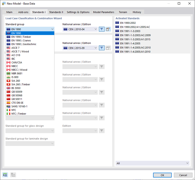
With Dlubal, you can safely and easily design structures all over the world. Select from a large number of standards in the Base Data. You can also decide whether to create the combinations automatically.
The following standards are available:
-
 EN 1990
 -
EN 1990 | Timber
-
EN 1990 | Road Bridges
-
EN 1990 | Cranes
-
EN 1990 | Geotechnical Engineering
-
EN 1990 | Base + Timber
-
EN 15512
-
 ASCE 7
 -
ASCE 7 | Timber
-
ACI 318
-
IBC
-
 CAN/CSA
 -
NBC
-
NBC | Timber
-
 NBR 8681
 -
 IS 800
 -
 SIA 260
 -
SIA 260 | Timber
-
 BS 5950
 -
 GB 50009
 -
GB 50068
-
GB 50011
-
 CTE DB-SE
 -
 SANS 10160-1
 -
 NTC
NTC -
NTC | Timber
-
 AS/NZS 1170.0
 -
 SP 20.13330:2016
 -
 TSC | Steel
For the European standards (EC), the following National Annexes are available:
-
 DIN | 2012-08 (Germany)
 -
CEN | 2010-04 (European Union)
-
 BDS | 2013-03 (Bulgaria)
 -
BS | 2009-06 (United Kingdom)
-
 CSN | 2015-05 (Czech Republic)
 -
 CYS | 2010-06 (Cyprus)
 -
 DK | 2013-09 (Denmark)
 -
 ELOT | 2009-01 (Greece)
 -
 EVS-EN 1990:2002+NA:2002 (Estonia)
 -
 IS | 2010-04 (Ireland)
 -
 LST | 2012-01 (Lithuania)
 -
 LU | 2020-03 (Luxembourg)
 -
 LVS | 2015-01 (Latvia)
 -
 MS | 2010-02 (Malaysia)
 -
 NBN | 2015-05 (Belgium)
 -
 NEN | 2011-12 (Netherlands)
 -
 NF | 2011-12 (France)
 -
 NP | 2009-12 (Portugal)
 -
 NS | 2016-05 (Norway)
 -
 ÖNORM | 2013-03 (Austria)
 -
 PN | 2010-09 (Poland)
 -
 SFS | 2010-09 (Finland)
 -
 SIST | 2010-08 (Slovenia)
 -
 SR | 2006-10 (Romania)
 -
 SS | 2008-06 (Singapore)
 -
 SS | 2019-01 (Sweden)
 -
 STN | 2010-01 (Slovakia)
 -
 TKP | 2011-11 (Belarus)
 -
UNE | 2010-07 (Spain)
-
 UNI | 2010-10 (Italy)
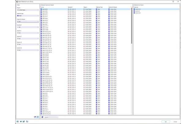
Discover the extensive cross-section and material libraries. They facilitate you the modeling of plate and beam structures. You can filter these databases and expand them with user-defined entries. You can also easily import and analyze special cross-sections from RSECTION.
- Available for cold-formed L, Z, C, channel, top-hat, and CL sections from the cross-section database, as well as for general cold-formed (non-perforated) SHAPE-THIN-9 sections
- Determination of the effective cross-section considering the local buckling and the distortional buckling
- Cross-section ultimate limit state, stability, and serviceability limit state designs according to EN 1993‑1‑3
- Design of local transverse forces for webs without stiffening
- Available for all National Annexes included in RF-/STEEL EC3
- Module extension RF-/STEEL Warping Torsion (license required) for stability analysis according to second-order analysis as stress analysis including consideration of the 7th degree of freedom (warping)
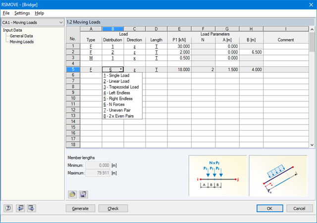
Sets of members with moving loads are selected graphically in the RFEM/RSTAB model. You can apply several different types of loads to one set of members at the same time.
By specifying the first load position, you can precisely display the load entering the runway of the continuous member. In the same way, it is possible to define whether a moving load consisting of various load applications is allowed to move beyond the end of continuous members (bridge) or not (crane runway).
The increment of the individual load positions is determined by the number of load cases generated for RFEM/RSTAB. You can also add loads to already existing RFEM/RSTAB load cases so that no additional superposition is required. Several load types are available, for example single, linear and trapezoidal loads as well as load pairs and several uniform concentrated loads.
It is possible to apply the loads in local and global directions. The application can refer to the true member length or to the projection in a global direction.
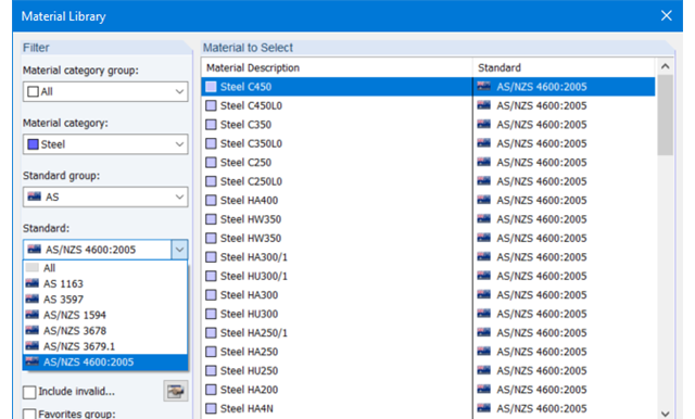
The material database in RFEM, RSTAB and SHAPE-THIN contains steels according to the Australian standard AS/NZS 4600:2005.
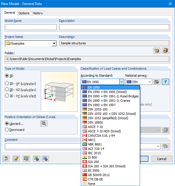
The Base Data dialog box includes a wide range of standards and the option to create combinations automatically. The following standards are available:
-
EN 1990:2002
-
EN 1990 + EN 1995:2004 (Timber)
-
EN 1990 + EN 1991-2; Road bridges
-
EN 1990 + EN 1991-3; Cranes
-
EN 1990 + EN 1997
-
to DIN 1055-100:2001-03
-
DIN 1055-100 + DIN 1052:2004-08 (timber)
-
DIN 1055-100 + DIN 18008 (Glass)
-
DIN 1052 (simplified) (timber)
-
DIN 18800:1990
-
ASCE 7‑10
-
ASCE 7-10 NDS (Wood)
-
ACI 318-14
-
IBC 2015
-
CAN/CSA S 16.1-94:1994
-
NBCC: 2005
-
NBR 8681
-
IS 800:2007
-
SIA 260:2003
-
SIA 260 + SIA 265:2003 (timber)
-
BS 5950-1:2000
-
GB 50009-2012
-
CTE DB-SE
For the European standards (EC), the following National Annexes are available:
-
DIN EN 1990/NA:2009-05 (Germany)
-
NBN EN 1990 - ANB: 2005 (Belgium)
-
BDS EN 1990:2003/NA:2008 (Bulgaria)
-
DK EN 1990/NA:2007-07 (Denmark)
-
SFS EN 1990/NA:2005 (Finland)
-
NF EN 1990/NA:2005/12 (France)
-
ELOT EN 1990:2009 (Greece)
-
UNI EN 1990/NA:2007-07 (Italy)
-
IS EN 1990:2002 + NA:2010 (Ireland)
-
LVS EN 1990:2003/NA:2010 (Latvia)
-
LST EN 1990/NA:2010-11 (Lithuania)
-
LU EN 1990/NA:2011-09 (Luxembourg)
-
MS EN 1990:2010 (Malaysia)
-
NEN EN 1990/NA:2006 (Netherlands)
- NS EN 1990/NA:2008 (Norway)
-
ÖNORM EN 1990:2007-02 (Austria)
-
NP EN 1990:2009 (Portugal)
-
PN EN 1990/NA:2004 (Poland)
-
SR EN 1990/NA:2006-10 (Romania)
-
SIST EN 1990: 2004/A1:2005 (Slovenia)
-
SS EN 1990:2008 (Singapore)
-
SS EN 1990/BFS 2010:28 (Sweden)
-
STN EN 1990/NA:2009-08 (Slovakia)
-
UNE EN 1990 2003 (Spain)
-
CSN EN 1990/NA:2004-03 (Czech Republic)
-
BS EN 1990/NA:2004-12 (the United Kingdom)
-
TKP EN 1990/NA:2011 (Belarus)
-
CYS EN 1990:2002 (Cyprus)
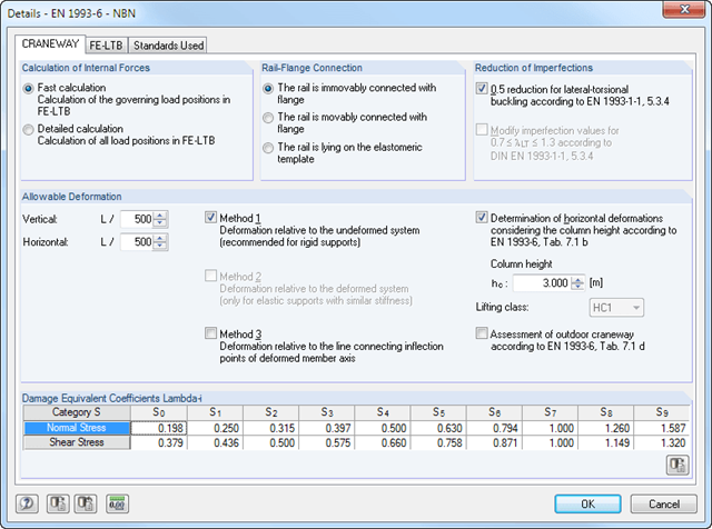
- Craneway and weld stress analysis
- Craneways and weld fatigue design
- Deformation,
- Plate buckling analysis for wheel load introduction
- Stability analysis for lateral torsional buckling according to the second-order analysis of torsional buckling (1D FEA element)
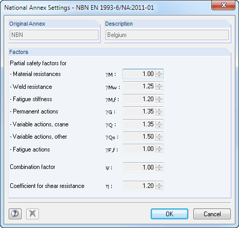
For the design according to Eurocode 3, the following National Annexes are available:
-
DIN EN 1993-6/NA:2010-12 (Germany)
-
NBN EN 1993-6/ANB:2011-03 (Belgium)
-
SFS EN 1993-6/NA:2010-03 (Finland)
-
NF EN 1993-6/NA:2011-12 (France)
-
UNI EN 1993-6/NA:2011-02 (Italy)
-
LST EN 1993-6/NA:2010-12 (Lithuania)
-
NEN EN 1993-6/NB:2012-05 (Netherlands)
-
NS EN 1993-6/NA:2010-01 (Norway)
-
SS EN 1993-6/NA:2011-04 (Sweden)
-
CSN EN 1993-6/NA:2010-03 (Czech Republic)
-
BS EN 1993-6/NA:2009-11 (United Kingdom)
-
CYS EN 1993-6/NA:2009-03 (Cyprus)
In addition to the National Annexes listed above, you can also define a specific NA, applying user-defined limit values and parameters.
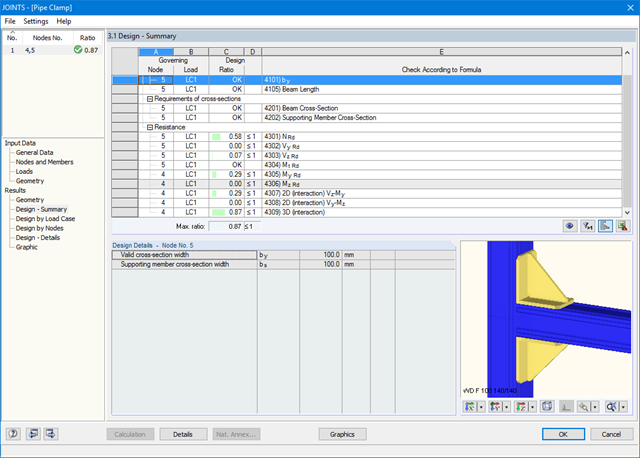
The existing loading is compared to the load resistances stored in the database. The program also performs the interaction of internal forces M, N, and Q.
After the design, all results are displayed in clearly arranged result tables; for example, by load case or by node.
You can visualize the joints graphically in the add-on module or in RFEM/RSTAB. In addition to the input and result data, including design details displayed in tables, you can add all graphics into the printout report. This way, comprehensible and clearly arranged documentation is guaranteed.
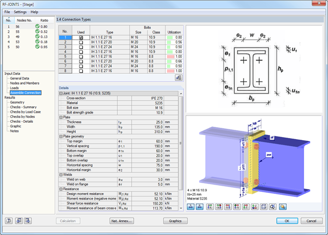
The extensive DSTV guideline is included in the database of the RF-/JOINTS Steel - DSTV add-on module. Each joint is characterized by a unique alphanumeric code.
The possible DSTV connections can be filtered out by the corresponding specifications for the DSTV connection type (IH, IW, IS, IG, and IK) and the used cross-section. This way, it is possible to determine the load-carrying capacity of the selected joint.
- General stress analysis
- Graphical and numerical results of stresses and stress ratios fully integrated in RFEM
- Flexible design with different layer compositions
- High efficiency due to few entries required
- Flexibility due to detailed setting options for basis and extent of calculations
- A local overall stiffness matrix of the surface in RFEM is generated on the basis of the selected material model and the layers contained. The following material models are available:
- Orthotropic
- Isotropic
- User-defined
- Hybrid (for combinations of material models)
- Option to save frequently used layer structures in a database
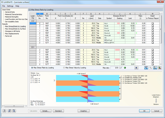
- Determination of basic, shear, and equivalent stresses
- In addition to the basic stresses, the required stresses according to DIN EN 1995-1-1 and the interaction of those stresses are available as results.
- Stress analysis for structural surfaces including simple or complex shapes
- Equivalent stresses calculated according to different approaches:
- Shape modification hypothesis (von Mises)
- Shear stress hypothesis (Tresca)
- Normal stress hypothesis (Rankine)
- Principal strain hypothesis (Bach)
- Calculation of transversal shear stresses according to Mindlin or Kirchhoff, or user-defined specifications
- Serviceability limit state design by checking surface displacements
- User-defined specifications of limit deflections
- Possibility to consider layer coupling
- Detailed results of individual stress components and ratios in tables and graphics
- Results of stresses for each layer in the model
- Parts list of designed surfaces
- Possible coupling of layers entirely without shear
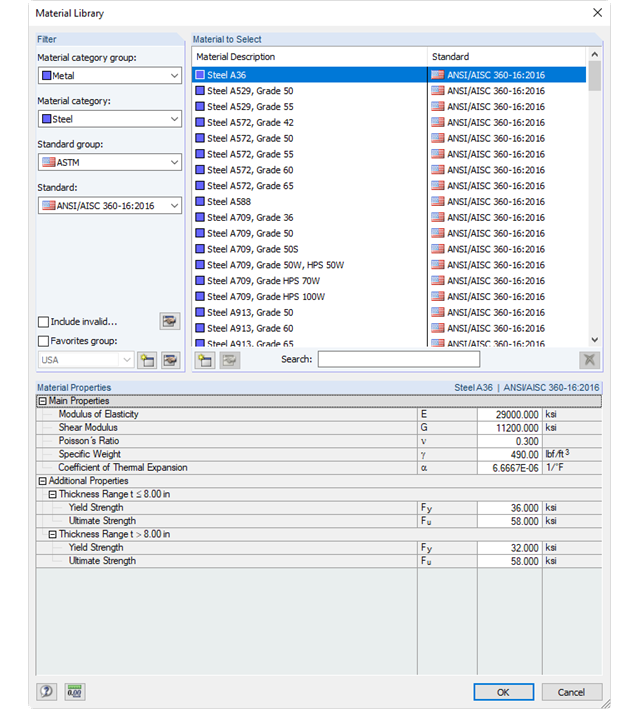
Extensive cross‑section and material libraries facilitate the modeling of plate and beam structures. These databases can be filtered and expanded with user-defined entries. It is possible to import and analyze special cross‑sections from SHAPE‑THIN and SHAPE‑MASSIVE.
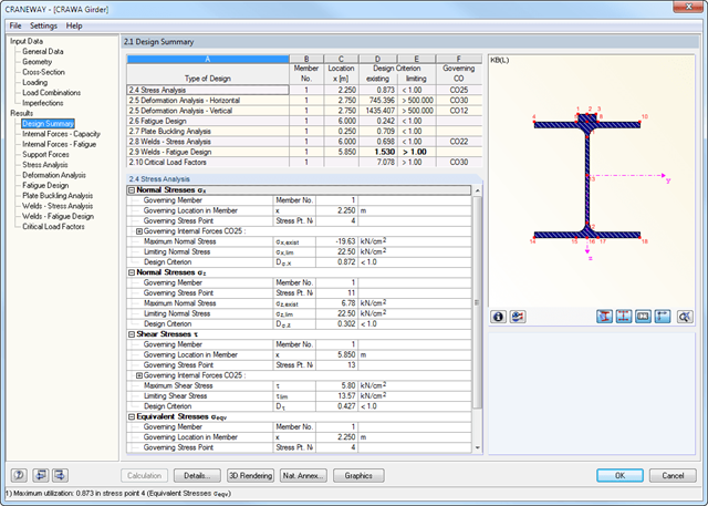
All results are arranged in result windows sorted by different topics. The design values are illustrated in the corresponding cross-section graphic. The design details cover all intermediate values.
General Stress Analysis
CRANEWAY performs the general stress analysis of a craneway girder by calculating the existing stresses and comparing them with the limit normal, limit shear, and limit equivalent stresses. Welds are also subjected to the general stress analysis with regard to parallel and vertical shear stresses and their superposition.
Fatigue Design
Fatigue design is performed for up to three cranes operating at the same time, based on the nominal stress concept according to EN 1993-1-9. In the case of fatigue design according to DIN 4132, a stress curve of crane passages is recorded for each stress point and evaluated according to the Rainflow method.
Buckling Analysis
Buckling analysis considers the local introduction of wheel loads according to the EN 1993-6 or DIN 18800-3 standards.
Deformation,
Deformation analysis is performed separately for the vertical and horizontal directions. The available related displacements are compared to the allowable values. You can specify the allowable deformation ratios individually in the calculation parameters.
Lateral-torsional buckling analysis
The lateral-torsional buckling analysis is performed in accordance with the second-order analysis for torsional buckling considering imperfections. The general stress analysis has to be fulfilled with the critical load factor greater than 1.00. As a result, CRANEWAY displays the corresponding critical load factor for all load combinations of the stress analysis.
Support forces
The program determines all support forces on the basis of the characteristic loads, including dynamic factors.
During the calculation, crane loads are generated in predefined distances as load cases of the crane runway. The load increment for cranes moving across the crane runway can be set individually.
The program analyzes all combinations of the respective limit states (ULS, fatigue, deformation, and support forces) for each crane position. In addition, there are comprehensive setting options for specification of the FE calculation, such as length of finite elements or break-off criteria.
The internal forces of a crane runway girder are calculated on an imperfect structural model according to the second-order analysis for torsional buckling.
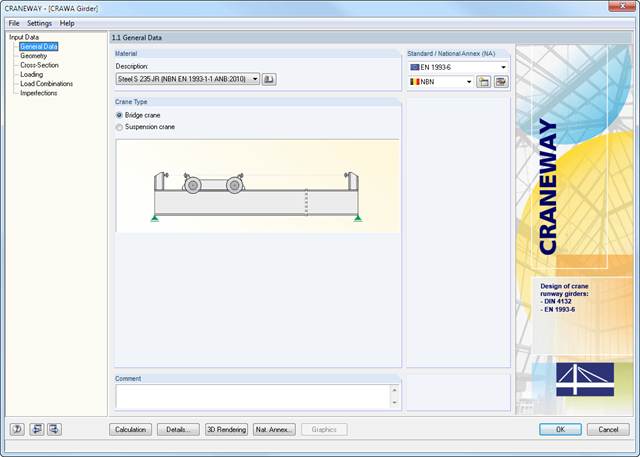
Geometry, material, cross-section, action, and imperfection data are entered in clearly arranged input windows:
Geometry
- Quick and convenient data input
- Definition of support conditions based on various support types (hinged, hinged movable, rigid, and user-defined, as well as lateral on upper or bottom flange)
- Optional specification of warping restraint
- Variable arrangement of rigid and deformable support stiffeners
- Possibility to insert hinges
CRANEWAY Cross-Sections
- I-shaped rolled cross-sections (I, IPE, IPEa, IPEo, IPEv, HE-B, HE-A, HE-AA, HL, HE-M, HE, HD, HP, IPB-S, IPB-SB, W, UB, UC, and other cross-sections according to AISC, ARBED, British Steel, Gost, TU, JIS, YB, GB, and others) combinable with section stiffener on the upper flange (angles or channels) as well as rail (SA, SF) or splice with user-defined dimensions
- Unsymmetrical I-sections (type IU) also combinable with stiffeners on the upper flange as well as with rail or splice
Actions
It is possible to consider the actions of up to three simultaneously operated cranes. You can simply select a standard crane from the library. You can also enter data manually:
- Number of cranes and crane axles (maximum of 20 axles per crane), center distances, position of crane buffers
- Classification in damage classes with editable dynamic factors according to EN 1993-6, and in lifting classes and exposure categories according to DIN 4132
- Vertical and horizontal wheel loads from self-weight, hoist load, mass forces from drive, as well as loads from skewing
- Axial loading in driving direction as well as buffer forces with user-defined eccentricities
- Permanent and variable secondary loads with user-defined eccentricities
Imperfections
- The imperfection load applies in compliance with the first natural vibration mode - either identically for all load combinations to be designed, or individually for each load combination, as mode shapes may vary depending on the load.
- Convenient tools available for scaling the mode shapes (rise determination of inclination and precamber).
.png?mw=640&hash=53c64389797699e939283ddbfc3d88485fcbfbf5)
- Full integration in RFEM/RSTAB, including import of all relevant loads
- General stress analysis with warping torsion according to elastic-elastic method
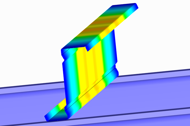
- Stability analysis of planar continuous members for buckling and lateral-torsional buckling
- Determination of critical load factor and thus of Mcr or Ncr (the factor can be used in RF-/LTB for the el/pl design)
- Lateral-torsional buckling analysis of any cross-section (also the SHAPE-THIN cross-sections)
- Design of members and sets of members with applied torsion (for example, crane girder)
- Optional determination of the limit load factor (critical load factor)
- Display of eigenmodes and torsional modes on the rendered cross-section
- Wide range of tools for determining shear panels and rotational restraints (such as corrugated sheets, purlins, bracings)
- Easy determination of discrete springs such as warp springs from end plates or rotational springs from columns
- Graphical selection of load application points on a cross-section (upper chord, centroid, lower chord, or any other point)
- Free arrangement of eccentric nodal and line supports on a cross-section
- Determination of value for inclination or precamber by means of eigenvalue analysis
- Special warping releases applicable for definition of warping conditions on transitions
.png?mw=640&hash=bfcf1f2df022078fffe5fbe15ce863c80a8534c1)
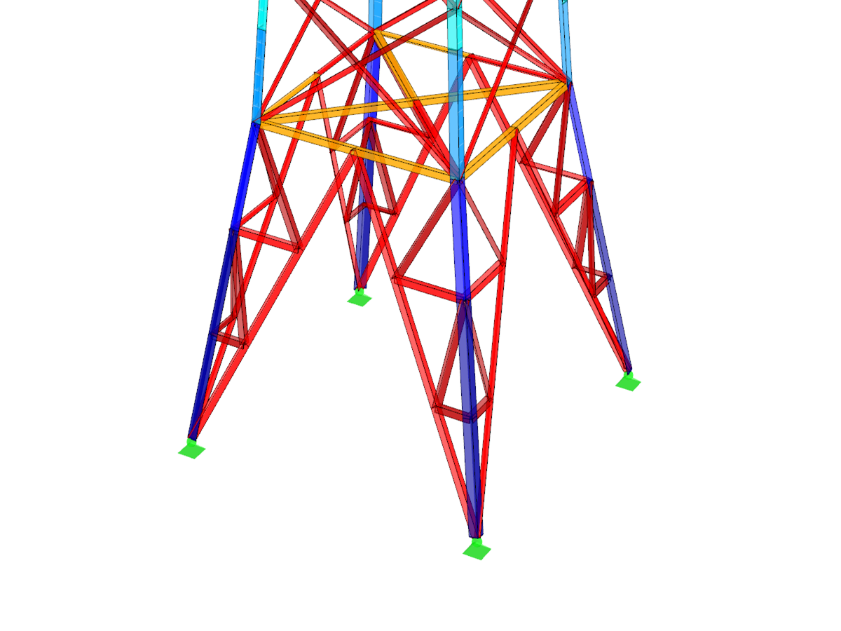
- Generation of triangular or rectangular tower types
- Access to the extensive material and cross-section library of RFEM/RSTAB
- Simple definition of geometry using tower segments
- Databases for vertical, horizontal, and inner bracing types
- Easy export of generated model data to RFEM/RSTAB
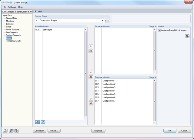
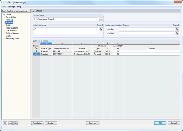
After creating the entire structure in RFEM/RSTAB, the individual structural components as well as load cases and combinations are assigned to the corresponding construction stages. For each construction stage, you can modify for example release definitions of members and supports.
Thus, it is possible to model structural modifications, such as those that occur when bridge girders are successively grouted or when columns are settled. The load cases and load combinations already created in RFEM/RSTAB are divided into "Permanent Loading" and "Temporary Loading" in the add-on module.
The defined temporary loads are superimposed by permanent loads. This way, it is possible to determine the maximum internal forces of different crane positions or to consider temporary mounting loads available only in one construction stage.
- Simple definition of construction stages in the RFEM/RSTAB structure including visualization
- Addition, removal, and modification of member, surface, and solid properties (such as member hinges, surface eccentricities, degrees of freedom for supports, and others)
- Optional superposition of construction stages with additional temporary loads; for example, mounting loads or mounting cranes, and others
- Consideration of nonlinear effects such as failure of a tension member, elastic foundations, or nonlinear supports
- Numerical and graphical result display for individual construction stages or as an envelope (Max/Min) of all construction stages
- Detailed printout report including all structural and load data of each construction stage
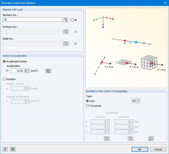
This generator creates loads as a result of an acceleration or rotation (e.g. from tower cranes), which acts on specific objects of the model.
The mass is determined from the self-weight.
More Information