
Using the "Damper" member type, you can define a damping coefficient, a spring constant, and a mass. This member type extends the possibilities within the Time History Analysis.
With regard to viscoelasticity, the "Damper" member type is similar to the Kelvin-Voigt model, which consists of the damping element and an elastic spring (both connected in parallel).
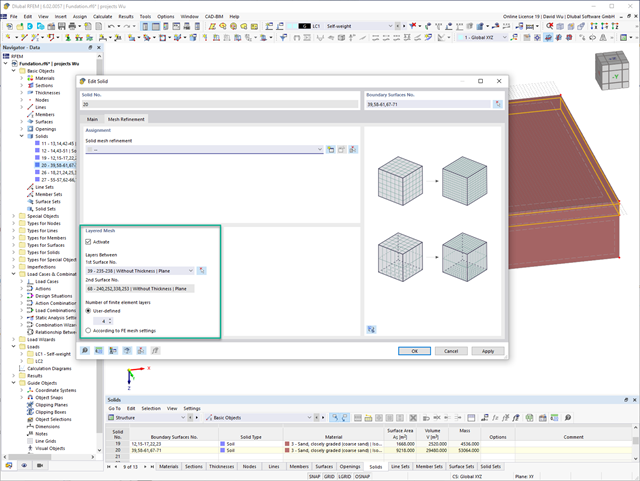
For the meshing of solids, you have the option of arranging a layered FE mesh. This option allows you to perform a defined division of the solid with finite elements between two parallel surfaces.
Go to Explanatory Video
- Many predefined components: Allow easy input of typical connection situations, such as end plates, angles, multi-wall sheets, cleats, fin plates
- Universally applicable basic components (plates, welds, bolts, auxiliary planes) for entering complex connection situations
- Graphical display of the connection geometry that is updated in parallel with the input
- The Steel Joints Template included in the add-on allows you to select from several connection types and, and once selected, it will be applied to your model.
- Wide range of cross-section shapes: Includes I-sections, channel sections, angles, T-sections, built-up cross-sections, RHS (rectangular hollow sections), and thin-walled sections
- The Template covers connections from three general categories: Rigid, Pinned, Truss
- Automatic adaptation of the connection geometry, even if the structural components are subsequently edited, based on the relative relation of the components

- The program performs a plausibility check in parallel with the input to quickly detect missing entries or collisions.
- If an error occurs, an error message appears describing the problem.

- Calculation of stationary incompressible turbulent wind flow using the SimpleFOAM solver from the OpenFOAM® software package
- Numerical scheme according to the first and second order
- Turbulence models RAS k-ω and RAS k-ε
- Consideration of surface roughness depending on model zones
- Model design via VTP, STL, OBJ, and IFC files
- Operation via bidirectional interface of RFEM or RSTAB for importing model geometries with standard-based wind loads and exporting wind load cases with probe-based printout report tables
- Intuitive model changes via drag & drop and graphical adjustment assistance
- Generation of a shrink-wrap mesh envelope around the model geometry
- Consideration of environmental objects (buildings, terrain, and so on)
- Height-dependent description of the wind load (wind speed and turbulence intensity)
- Automatic meshing depending on a selected depth of detail
- Consideration of layer meshes near the model surfaces
- Parallelized calculation with optimal utilization of all processor cores of a computer
- Graphical output of the surface results on the model surfaces (surface pressure, Cp coefficients)
- Graphical output of the flow field and vector results (pressure field, velocity field, turbulence – k-ω field, and turbulence – k-ε field, velocity vectors) on Clipper/Slicer planes
- Display of 3D wind flow via animated streamline graphics
- Definition of point and line probes
- Multilingual user interface (German, English, Czech, Spanish, French, Italian, Polish, Portuguese, Russian, and Chinese)
- Calculations of several models in one batch process
- Generator for creating rotated models to simulate different wind directions
- Optional interruption and continuation of the calculation
- Individual color panel per result graphic
- Display of diagrams with separate output of results on both sides of a surface
- Output of the dimensionless wall distance y+ in the mesh inspector details for the simplified model mesh
- Determination of the shear stress on the model surface from the flow around the model
- Calculation with an alternative convergence criterion (you can select between the residual types pressure or flow resistance in the simulation parameters)
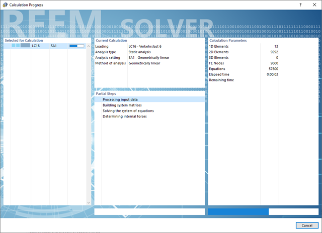
Do you have to calculate multiple load combinations in your models? Then several solvers (one per core) are initiated in parallel, each of which calculates a load combination. This ensures a better utilization of the cores and thus faster calculations.
Go to Explanatory Video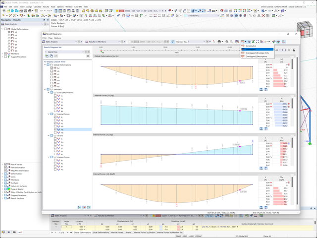
Discover the new features in the result diagram window:
- Parallel work in the result diagram window and in the model
- Optional overlapping display of results (for example, several similar structural components in one image)
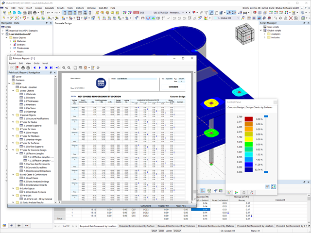
Discover the fundamentally revised and optimized printout report. It offers you the following innovations, among other things:
- Quick creation due to non-modal printout report environment (parallel work in program and report possible)
- Interactive modification of chapters as well as creation of new user-defined chapters
- Import of PDFs, formulas, 3D graphics, and so on
- Output of the design check formulas used in the design (including a reference to the used equation from the standard)
- Modern printout report design
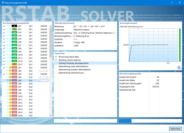
Also in this case, RSTAB will certainly convince you. With the powerful calculation kernel, its optimized networking and support of multi-core processor technology, the Dlubal structural analysis program is far ahead. This allows you to calculate more linear load cases and load combinations using several processors in parallel without using additional memory. The stiffness matrix only has to be created once. Thus, it is possible for you to calculate even large systems with the fast and direct solver.
Do you have to calculate multiple load combinations in your models? The program initiates several solvers in parallel (one per core). Each solver then calculates a load combination for you. This leads to better utilization of the cores.
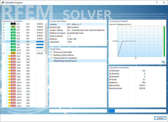
You can systematically follow the development of the deformation displayed in a diagram during the calculation, and thus precisely evaluate the convergence behavior.

Compared to the RF-FORM-FINDING add-on module (RFEM 5), the following new features have been added to the Form-Finding add-on for RFEM 6:
- Specification of all form-finding load boundary conditions in one load case
- Storage of form-finding results as initial state for further model analysis
- Automatic assignment of the form-finding initial state via combination wizards to all load situations of a design situation
- Additional form-finding geometry boundary conditions for members (unstressed length, maximum vertical sag, low-point vertical sag)
- Additional form-finding load boundary conditions for members (maximum force in member, minimum force in member, horizontal tension component, tension at i-end, tension at j-end, minimum tension at i-end, minimum tension at j-end)
- Material types "Fabric" and "Foil" in material library
- Parallel form-findings in one model
- Simulation of sequentially building form-finding states in connection with the Construction Stages Analysis (CSA) add-on

Did you know? The structural optimization in the programs RFEM and RSTAB is a completion of the parametric input. It is a parallel process beside the actual model calculation with all its regular calculation and design definitions. The add-on assumes that your model or block is built with a parametric context and is controlled in its entirety by global control parameters of the "optimization" type. Therefore, these control parameters have a lower and upper limit and a step size to delimit the optimization range. If you want to find optimal values for the control parameters, you have to specify an optimization criterion (for example, minimum weight) with the selection of an optimization method (for example, particle swarm optimization).
You can already find the cost and CO2 emission estimation in the material definitions. You can activate both options individually in each material definition. The estimation is based on a unit for unit cost or unit emission for members, surfaces, and solids. In this case, you can select whether to specify the units by weight, volume, or area.

- Selection of nodes in the RFEM model, automatic recognition and assignment of the members connected to the node
- Many predefined components available for easy input of typical connection situations (for example, end plates, cleats, fin plates)
- Universally applicable basic components (plates, welds, auxiliary planes) for entering complex connection situations
- No manual editing of the FE model required by the user, the essential calculation settings can be changed via the configuration settings
- Automatic adaptation of the connection geometry, even if the members are subsequently edited, due to the relative relation of the components to each other
- Parallel to the input, a plausibility check is carried out by the program to quickly detect missing input or collisions, for example
- Graphical display of the connection geometry that is updated in parallel with the input
Convince yourself by the powerful calculation kernel, its optimized networking and support of multi-core processor technology. This provides you with the advantages, such as parallel calculations of linear load cases and load combinations using several processors without additional demands on the RAM. The stiffness matrix only has to be created once. Thus, you can calculate even large systems with the fast direct solver.
If you need to calculate multiple load combinations in your models, the program initiates several solvers in parallel (one per core). Each solver then calculates a load combination, which improves the core utilization.
You can systematically follow the development of the deformation displayed in a diagram during the calculation, and thus precisely evaluate the convergence behavior.
- 3D incompressible wind flow analysis with OpenFOAM® software package
- Direct model import from RFEM or RSTAB including neighboring and terrain models (3DS, IFC, STEP files)
- Model design via STL or VTP files independent of RFEM or RSTAB
- Simple model changes using Drag and Drop and graphical adjustment assistance
- Automatic corrections of the model topology with shrink wrap networks
- Option to add objects from the environment (buildings, terrain ...)
- Wind load determined over the height of the building, depending on standard-specific parameters (velocity, turbulence intensity)
- K-epsilon and K-omega turbulence models
- Automatic mesh generation adjusted to the selected depth of detail
- Parallel calculation with optimal utilization of the capacity of multicore computers
- Results in just minutes for low-resolution simulations (up to 1 million cells)
- Results within a few hours for simulations with medium/high resolution (1‑10 million cells)
- Graphical display of results on the Clipper/Slicer planes (scalar and vector fields)
- Graphical display of streamlines
- Streamline animation (optional video creation)
- Definition of point and line probes
- Display of aerodynamic pressure coefficients
- Graphical display of turbulence properties in the wind field
- Optional meshing using the boundary layer option for the area near the model surface
- Consideration of rough model surfaces possible
- Optional use of a seond-order numerical Order
- Multilingual user interface (for example, German, English, Spanish, French)
- Documentation possible in the RFEM and RSTAB printout report
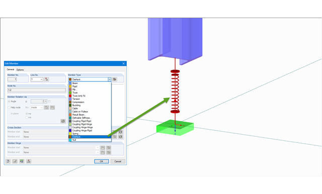
The member type 'Dashpot' can be used for time history analyzes in RFEM/RSTAB with the add-on modules RF-/DYNAM Pro - Forced Vibrations and RF-/DYNAM Pro - Nonlinear Time History. This linear viscous damping element considers forces dependent on velocity.
With regard to viscoelasticity, the member type 'Dashpot' is similar to the Kelvin-Voigt model, which consists of the damping element and an elastic spring (both connected in parallel).
.png?mw=640&hash=c1087880acc023575381bb136280b0c348568350)
- Design of hinged connections
- Biaxial inclination of the connected member (for example, a jack rafter joint)
- Connection of any number of members on one node for the type "Main member only"
- Screw diameter 6 mm – 12 mm
- Automatic check of the minimum distance between screws
- Optional free definition of screw distances
- Transfer of eccentricity from RFEM/RSTAB
- Crosswise or parallel screw alignment
- Definition of up to 16 screws in a row
- Graphical visualization of joints in the add-on module and in RFEM/RSTAB
- Performing all required designs
- Design of the following geometrical types:
- Symmetrical / asymmetrical
- Half-frame
- Column sloping inside / outside
- Intermediate piece with / without
- Direction of lamellas can be defined as parallel to inner or outer edge
- For design according to EC 5 (EN 1995), the following National Annexes are available:
-
 DIN EN 1995-1-1/NA:2013-08 (Germany)
 -
 NBN EN 1995-1-1/ANB:2012-07 (Belgium)
 -
 DK EN 1995-1-1/NA:2011-12 (Denmark)
 -
 SFS EN 1995-1-1/NA:2007-11 (Finland)
 -
 NF EN 1995-1-1/NA:2010-05 (France)
 -
 UNI EN 1995-1-1/NA:2010-09 (Italy)
 -
 NEN EN 1995-1-1/NB:2007-11 (Netherlands)
 -
 ÖNORM B 1995-1-1:2015-06 (Austria)
 -
 PN EN 1995-1-1/NA:2010-09 (Poland)
 -
 SS EN 1995-1-1 (Sweden)
 -
 STN EN 1995-1-1/NA:2008-12 (Slovakia)
 -
 SIST EN 1995-1-1/A101:2006-03 (Slovenia)
 -
 CSN EN 1995-1-1:2007-09 (Czech Republic)
 -
 BS EN 1995-1-1/NA:2009-10 (the United Kingdom)
-
- Simple geometry input with illustrative graphics
- Automatic generation of wind and snow loads
- Automatic creation of required combinations for the ultimate and serviceability limit states, as well as fire resistance design
- Possibility to define load cases and load applications
- Extensive material library for both standards
- Optional extension of material library by further materials
- Extensive library of permanent loads
- Allocation of framework to service classes and specification of service class categories
- Determination of design ratios, support forces, and deformations
- Info icon indicating successful or failed design
- Color reference scales in result tables
- Direct data export to MS Excel
- DXF interface for preparation production documents in CAD
- Program languages: English, German, Czech, Italian, Spanish, French, Portuguese, Polish, Chinese, Dutch, and Russian
- Verifiable printout report, including all required designs. Printout report available in many output languages; for example, English, German, French, Italian, Spanish, Russian, Czech, Polish, Portuguese, Chinese, and Dutch.
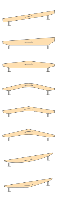
- Design of the following beam types:
- Parallel beam
- Monopitch roof beam
- Double tapered beam
- Arched beam
- Pitched cambered beam with constant height
- Pitched cambered beam with variable height
- Fish Beam - Parabolic
- Fish beam - Linear with rounding in central area
- Unsymmetrical beams with and without cantilevers
- Arrangement of a loose ridge wedge
- Optional consideration of stiffening elements for transversal tension
- Two design types available for stiffening elements concerning transversal tension:
- Constructive if required
- Full absorption of tension stresses perpendicular to grain
- Calculation of required number of stiffening elements for transversal tension and graphical representation of the arrangement in the beam
- Simple geometry input with illustrative graphics
- Convenient generation of snow loads according to EN 1991-1-3 or DIN 1055:2005, Part 5
- Automatic determination of wind loads according to EN 1991-1-4 or DIN 1055:2005, Part 4
- User-defined load cases and load applications
- Automatic generation of all possible load combinations
- Connection to MS Excel and access via COM interface
- Material library for both standards
- For design according to EC 5 (EN 1995), the following National Annexes are available:
-
DIN EN 1995-1-1/NA:2013-08 (Germany)
-
NBN EN 1995-1-1/ANB:2012-07 (Belgium)
-
DK EN 1995-1-1/NA:2011-12 (Denmark)
-
SFS EN 1995-1-1/NA:2007-11 (Finland)
-
NF EN 1995-1-1/NA:2010-05 (France)
-
UNI EN 1995-1-1/NA:2010-09 (Italy)
-
NEN EN 1995-1-1/NB:2007-11 (Netherlands)
-
ÖNORM B 1995-1-1:2015-06 (Austria)
-
PN EN 1995-1-1/NA:2010-09 (Poland)
-
SS EN 1995-1-1 (Sweden)
-
STN EN 1995-1-1/NA:2008-12 (Slovakia)
-
SIST EN 1995-1-1/A101:2006-03 (Slovenia)
-
CSN EN 1995-1-1:2007-09 (Czech Republic)
-
BS EN 1995-1-1/NA:2009-10 (the United Kingdom)
-
- Extensive library of permanent loads
- Allocation of a structure to service class, and specification of service class categories
- Determination of design ratios, support forces, and deformations
- Info icon indicating successful or failed design
- Color reference scales in result tables
- Direct data export to MS Excel
- DXF interface for preparation production documents in CAD
- Program languages: English, German, Czech, Italian, Spanish, French, Portuguese, Polish, Chinese, Dutch, and Russian
- Verifiable printout report, including all required designs. Printout report available in many output languages; for example, English, German, French, Italian, Spanish, Russian, Czech, Polish, Portuguese, Chinese, and Dutch.
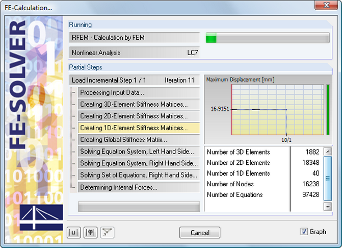
The equation solver includes an optimized FE mesh generator and supports the latest multi-core processor and 64-bit technology. It enables parallel calculations of linear load cases and load combinations using several processors without additional demands on the RAM: The stiffness matrix only has to be created once. The 64-bit technology and the enhanced RAM options allow for calculation of complex structural systems using the fast and direct equation solver.
The development of the deformation is displayed in a diagram during the calculation. This way, you can easily evaluate the convergence behavior.
All results are arranged in result windows sorted by different topics. The design values are illustrated in the corresponding cross-section graphic. The design details cover all intermediate values.
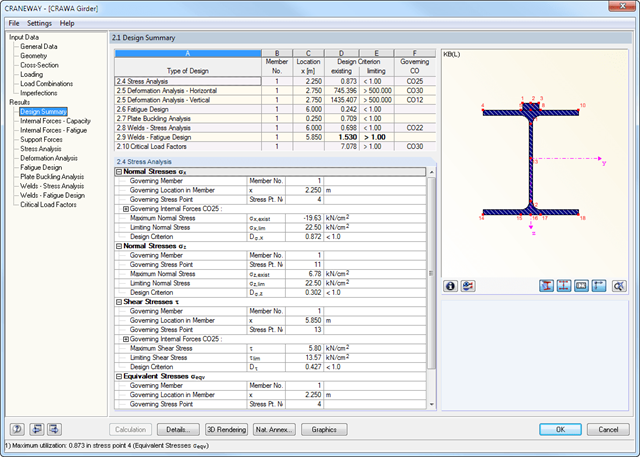
General Stress Analysis
CRANEWAY performs the general stress analysis of a craneway girder by calculating the existing stresses and comparing them with the limit normal, limit shear, and limit equivalent stresses. Welds are also subjected to the general stress analysis with regard to parallel and vertical shear stresses and their superposition.
Fatigue Design
Fatigue design is performed for up to three cranes operating at the same time, based on the nominal stress concept according to EN 1993-1-9. In the case of fatigue design according to DIN 4132, a stress curve of crane passages is recorded for each stress point and evaluated according to the Rainflow method.
Buckling Analysis
Buckling analysis considers the local introduction of wheel loads according to the EN 1993-6 or DIN 18800-3 standards.
Deformation,
Deformation analysis is performed separately for the vertical and horizontal directions. The available related displacements are compared to the allowable values. You can specify the allowable deformation ratios individually in the calculation parameters.
Lateral-torsional buckling analysis
The lateral-torsional buckling analysis is performed in accordance with the second-order analysis for torsional buckling considering imperfections. The general stress analysis has to be fulfilled with the critical load factor greater than 1.00. As a result, CRANEWAY displays the corresponding critical load factor for all load combinations of the stress analysis.
Support forces
The program determines all support forces on the basis of the characteristic loads, including dynamic factors.
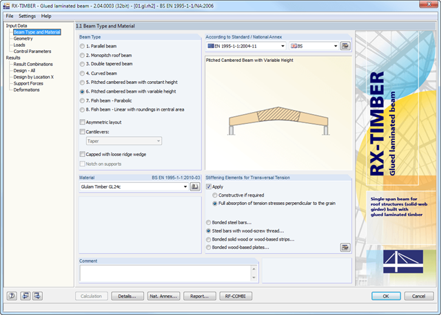
RX-TIMBER Glued-Laminated Beam designs wide-span glulam beams of eight different beam types (parallel, monopitch roof, double tapered beam, and others).
It is possible to consider typical stiffening elements for transversal tension; for example, bonded steel bars.
RX-TIMBER Glued-Laminated Beam | Design of Glued-Laminated Beams