16 Results
View Results:
Sort by:
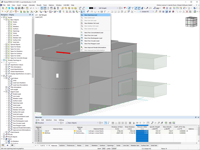
This new feature allows you to easily define opening loads (for example, wind loads) for flat loads on openings.
- Deformation analyses of reinforced concrete surfaces without or with cracks (state II) by applying the approximation method (for example, deformation analysis according to ACI 318-19, 24.3.2.5 or EN 1992‑1‑1, Cl. 7.4.3 )
- Tension stiffening of concrete applied between cracks
- Optional consideration of creep and shrinkage
- Graphical representation of results integrated in RFEM, such as deformation or sag of a flat slab
- Clear numerical result display in the detail dialog box
- Complete integration of results in the RFEM printout report

Wind loads are also not a problem in your design. You can automatically generate wind loads as member loads or area loads (RFEM) on the following structural components:
- Vertical walls
- Flat roofs
- Monopitch roofs
- Duopitch/troughed roofs
- Vertical walls with duopitch roof
- Vertical walls with flat/monopitch roof
The following standards are available to you:
-
 EN 1991-1-4 (including National Annexes)
 -
 ASCE 7
 -
 CTE DB-SE-AE
 -
 GB 50009
- Design of the following geometrical types:
- Single-span beams with and without cantilevers
- Continuous beams with and without cantilevers
- Hinged girder system (Gerber beams) with and without cantilevers
- Automatic generation of wind and snow loads
- Automatic creation of required combinations for the ultimate and serviceability limit states, as well as fire resistance design
- For design according to EC 5 (EN 1995), the following National Annexes are available:
-
 DIN EN 1995-1-1/NA:2013-08 (Germany)
 -
 NBN EN 1995-1-1/ANB:2012-07 (Belgium)
 -
 DK EN 1995-1-1/NA:2011-12 (Denmark)
 -
 SFS EN 1995-1-1/NA:2007-11 (Finland)
 -
 NF EN 1995-1-1/NA:2010-05 (France)
 -
 UNI EN 1995-1-1/NA:2010-09 (Italy)
 -
 NEN EN 1995-1-1/NB:2007-11 (Netherlands)
 -
 ÖNORM B 1995-1-1:2015-06 (Austria)
 -
 PN EN 1995-1-1/NA:2010-09 (Poland)
 -
 SS EN 1995-1-1 (Sweden)
 -
 STN EN 1995-1-1/NA:2008-12 (Slovakia)
 -
 SIST EN 1995-1-1/A101:2006-03 (Slovenia)
 -
 CSN EN 1995-1-1:2007-09 (Czech Republic)
 -
 BS EN 1995-1-1/NA:2009-10 (the United Kingdom)
-
- Consideration of optimization options by user specifications according to the respective standard:
- Shear force reduction of single loads near support
- Shear force reduction of load introduction at the cross-section top point
- Moment redistribution in support zone
- Reduction of torsional stress by means of user-defined entry of moment
- Increase of bending stiffnesses for flat-ended or edgewise bending strains
- Simple geometry input with illustrative graphics
- Extensive material library for both standards
- Optional extension of material library by further materials
- Extensive library of permanent loads
- Allocation of framework to service classes and specification of service class categories
- Determination of design ratios, support forces, and deformations
- Info icon indicating successful or failed design
- Color reference scales in result tables
- Direct data export to MS Excel
- Program languages: English, German, Czech, Italian, Spanish, French, Portuguese, Polish, Chinese, Dutch, and Russian
- Verifiable printout report, including all required designs. Printout report available in many output languages; for example, English, German, French, Italian, Spanish, Russian, Czech, Polish, Portuguese, Chinese, and Dutch.
- Direct import of stp files from various CAD programs

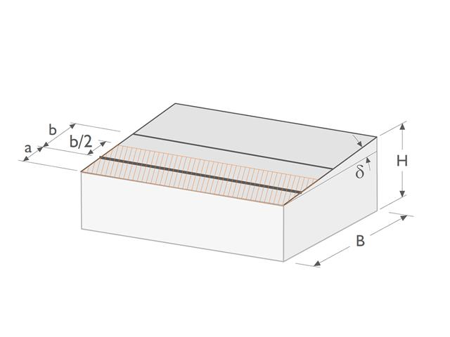
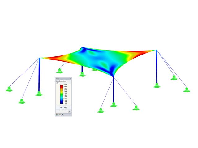
The nonlinear calculation adopts the real mesh geometry of planar, buckled, simple curved, or double curved surface components from the selected cutting pattern and flattens this surface component in compliance with the minimization of distortion energy, assuming defined material behavior.
In simplified terms, this method attempts to compress the mesh geometry in a press, assuming frictionless contact, and to find the state in which the stresses from flattening in the component are in equilibrium in the plane. This way, minimum energy and optimum accuracy of the cutting pattern are achieved. Compensation for warp and weft as well as compensation for boundary lines are considered. Then, the defined allowances on boundary lines are applied to the resulting planar surface geometry.
Features:
- Minimization of distortion energy in the flattening process for very accurate cutting patterns
- Application for almost all mesh arrangements
- Recognition of adjacent cutting pattern definitions to keep the same length
- Mesh application for main calculation
- Planar and geodesic cutting lines
- Flattening of double-curved surface parts of tensioned membranes or pneumatic cushions
- Definition of cutting patterns by using boundary lines which are not required to be connected
- Sophisticated flattening based on the minimum energy theory
- Welding and boundary allowances
- Uniform or linear compensation in warp and weft direction
- Possibility of different compensations for boundary lines
- Adaptable data organisation (any additional modification of input data is considered up to the final "weld")
- Graphical display of cutting patterns
- Statistical information about each cutting pattern (width, length, size)
- Option to automatically generate cutting patterns from cells
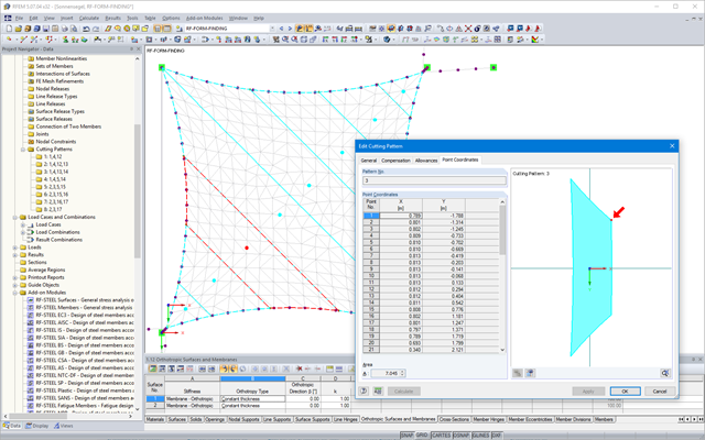
After the calculation, the "Point Coordinates" tab appears in the cutting pattern dialog box. In this tab, the result is displayed in the form of a table with coordinates and a surface in the graphical window. The coordinate table presents new flattened coordinates relative to the centroid of the cutting pattern for each mesh node. Furthermore, the cutting pattern with the coordinate system at the centroid is represented in the graphical window. When selecting a table cell, the respective node is displayed with an arrow in the graphic. In addition, the area of the cutting pattern is displayed below the node table.
Moreover, standard stress/strain results for each pattern are displayed in the RF‑CUTTING‑PATTERN load case in RFEM.
Features:
- Results in a table, including information about the cutting pattern
- Smart table relating to the graphic
- Results of flattened geometry in a DXF file
- Output of strains after flattening in order to evaluate the cutting patterns
- Results of strains after flattening for the evaluation of patterns
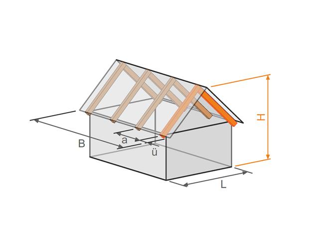
- Design of the following roof types:
- Flat Roof
- Monopitch roof
- Duopitch roof (symmetrical/asymmetrical)
- Definition of any additional support and free selection of degrees of freedom (additional free definition of translational and rotational spring stiffness of supports and hinges)
- Arrangement of up to five collar/tie beams, including intermediate support for duopitch roof
- Automatic generation of wind and snow loads
- Automatic generation of required combinations for the ultimate and serviceability limit states, as well as fire resistance design (additional definition of several member and nodal loads)
- For design according to EC 5 (EN 1995), the following National Annexes are available:
-
Germany DIN EN 1995-1-1/NA:2013-08 (Germany)
-
NBN EN 1995-1-1/ANB:2012-07 (Belgium)
-
 BDS EN 1995-1-1/NA:2012-02 (Bulgaria)
 -
DK EN 1995-1-1/NA:2011-12 (Denmark)
-
SFS EN 1995-1-1/NA:2007-11 (Finland)
-
NF EN 1995-1-1/NA:2010-05 (France)
-
 I S. EN 1995-1-1/NA:2010-03 (Ireland)
 -
UNI EN 1995-1-1/NA:2010-09 (Italy)
-
NEN EN 1995-1-1/NB:2007-11 (Netherlands)
-
ÖNORM B 1995-1-1:2015-06 (Austria)
-
PN EN 1995-1-1/NA:2010-09 (Poland)
-
SS EN 1995-1-1 (Sweden)
-
STN EN 1995-1-1/NA:2008-12 (Slovakia)
-
SIST EN 1995-1-1/A101:2006-03 (Slovenia)
-
CSN EN 1995-1-1:2007-09 (Czech Republic)
-
BS EN 1995-1-1/NA:2009-10 (the United Kingdom)
-
 CYS EN 1995-1-1/NA:2011-02 (Cyprus)
-
- Simple geometry input with illustrative graphics
- Input of tapered cantilevers with cut-to-grain on the bottom side of rafters
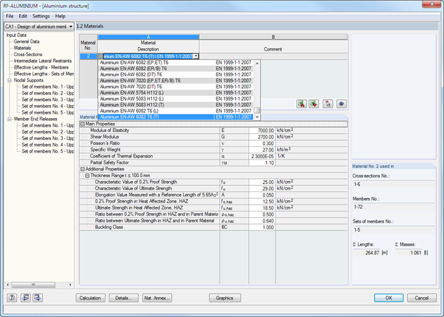
- Extensive material library that can be extended by user-defined materials
- Determination of design ratios, support forces, and deformations
- Color reference scales in result tables
- Direct data export to MS Excel
- Program languages: English, German, Czech, Italian, Spanish, French, Portuguese, Polish, Chinese, Dutch, and Russian
- Verifiable printout report, including all required designs. Printout report available in many output languages; for example, English, German, French, Italian, Spanish, Russian, Czech, Polish, Portuguese, Chinese, and Dutch.
- Design of tension, compression, bending, shear, and combined internal forces
- Stability analysis for flexural buckling, torsional buckling, and lateral-torsional buckling
- Automatic determination of critical buckling loads and critical moment for lateral-torsional buckling by means of integrated FEA program (eigenvalue analysis) from boundary conditions of loads and supports
- Optional application of discrete lateral supports to beams
- Automatic or manual cross-section classification
- Integration of parameters from National Annexes (NA) of the following countries:
-
DIN EN 1999-1-1/NA:2010-12 (Germany)
-
NBN EN 1999-1-1/ANB:2011-03 (Belgium)
-
DK EN 1999-1-1/NA:2013-05 (Denmark)
-
SFS EN 1999-1-1/NA:2016-12 (Finland)
-
 ELOT EN 1999-1-1/NA:2010-11 (Greece)
 -
IS EN 1999-1-1/NA:2010-03 (Ireland)
-
UNI EN 1999-1-1/NA:2011-02 (Italy)
-
 LST EN 1999-1-1/NA:2011-09 (Lithuania)
 -
 UNI EN 1999-1-1/NA:2011-02 (Italy)
 -
NEN EN 1999-1-1/NB:2011-12 (Netherlands)
-
PN EN 1999-1-1/NA:2011-01 (Poland)
-
SS EN 1999-1-1/NA:2011-04 (Sweden)
-
STN EN 1999-1-1/NA:2010-01 (Slovakia)
-
BS EN 1999-1-1/NA:2009 (the United Kingdom)
-
STN EN 1999-1-1/NA:2009-02 (Slovakia)
-
CYS EN 1999-1-1/NA:2009-07 (Cyprus)
-
- Serviceability limit state design for characteristic, frequent, or quasi-permanent design situation
- Consideration of transverse welds
- Variety of cross-sections provided; for example, I‑sections, C‑sections, rectangular hollow sections, square sections, angles with equal and unequal legs, flat steel, round bars
- Clearly arranged result tables
- Automatic cross-section optimization
- Detailed result documentation with references to the design equations used and described in the standard
- Filter and sorting options for results, including result lists by member, cross‑section, and x‑location, or by load cases, load combinations, and result combinations
- Result window of member slenderness and governing internal forces
- Parts list with weight and solid specifications
- Seamless integration in RFEM/RSTAB
- Metric and imperial units
In RX-TIMBER Frame, the following calculation settings are available:
- Design of ULS, SLS, and/or fire resistance Selection of designs to be performed
- Determination of displaying support forces and deformations
- Adjusting the recommended limit values for the deformation analyses
- Free definition of parameters for the fire resistance design performed according to the simplified method
- Increasing bending stiffnesses for flat‑ended bending strains
Separate design cases allow for a flexible analysis of specific actions as well as for individual stability analyses. You can define the design type to be performed in the Control Parameters window.
- For the design according to Eurocode 3, the following National Annexes are available:
-
DIN EN 1993-1-5/NA:2010-12 (Germany)
-
SFS EN 1993-1-5/NA:2006 (Finland)
-
NBN EN 1993-1-5/NA:2011-03 (Belgium)
-
UNI EN 1993-1-5/NA:2011-02 (Italy)
-
NEN EN 1993-1-5/NA:2011-04 (Netherlands)
-
 NS EN 1993-1-5/NA:2009-06 (Norway)
 -
CSN EN 1993-1-5/NA:2008-07 (Czech Republic)
-
CYS EN 1993-1-5/NA:2009-03 (Cyprus)
-
- In addition to the National Annexes listed above, you can also define a specific NA, applying user-defined limit values and parameters.
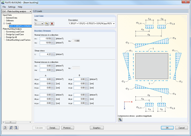
- Import of all relevant internal forces from RFEM/RSTAB by selecting numbers of members and buckling panels with determination of governing boundary stresses
- Summary of stresses in load cases with determination of governing load
- Different materials for stiffener and plate possible
- Import of stiffeners from an extensive library (flat plate and bulb flat steel, angle, T-section, channel, and trapezoidal sheeting)
- Determination of effective widths according to EN 1993-1-5 (Table 4.1 or 4.2) or DIN 18800, Part 3, Eq. (4)
- Optional calculation of critical buckling stresses according to analytical formulas of annexes A.1, A.2, and A.3 of EC 3, or by means of FEA calculation
- Designs (stress, deformation, torsional buckling) of longitudinal and transverse stiffeners
- Optional consideration of buckling effects according to DIN 18800, Part 3, Eq. (13)
- Photo-realistic representation (3D rendering) of buckling panel, including stiffeners, stress conditions, and buckling modes with animation
- Documentation of all input data and results in a verifiable printout report
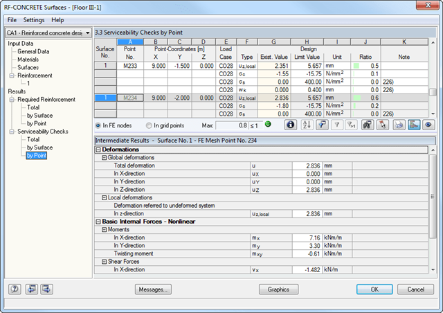
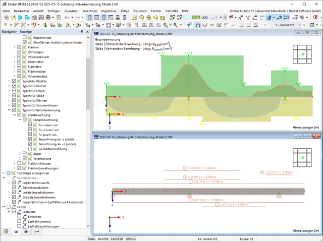
- Deformation analyses of reinforced concrete surfaces without or with cracks (state II) by applying the approximation method (for example, deformation analysis according to EN 1992-1-1, Cl. 7.4.3 )
- Tension stiffening of concrete applied between cracks
- Optional consideration of creep and shrinkage
- Graphical representation of results integrated in RFEM; for example, deformation or sag of a flat slab
- Numerical results clearly arranged in tables and graphical display of the results in the model
- Complete integration of results in the RFEM printout report
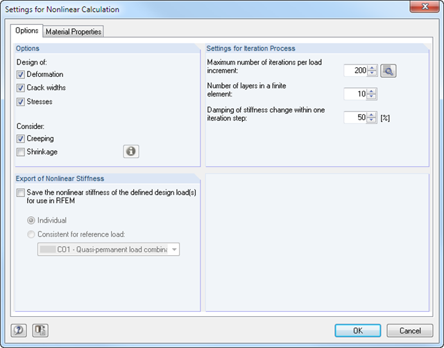
- Iterative nonlinear calculation of deformations for beam and plate structures consisting of reinforced concrete by determining the respective element stiffness subjected to the defined loads
- Deformation analyses of cracked reinforced concrete surfaces (state II)
- General nonlinear stability analysis of compression members made of reinforced concrete; for example, according to EN 1992-1-1, 5.8.6
- Tension stiffening of concrete applied between cracks
- Numerous National Annexes available for the design according to Eurocode 2 (EN 1992-1-1:2004 + A1:2014, see EC2 for RFEM)
- Optional consideration of long-term influences such as creep or shrinkage
- Nonlinear calculation of stresses in reinforcing steel and concrete
- Nonlinear calculation of crack widths
- Flexibility due to detailed setting options for basis and extent of calculations
- Graphical representation of results integrated in RFEM; for example, deformation or sag of a flat slab made of reinforced concrete
- Numerical results clearly arranged in tables and graphical display of the results in the model
- Complete integration of results in the RFEM printout report
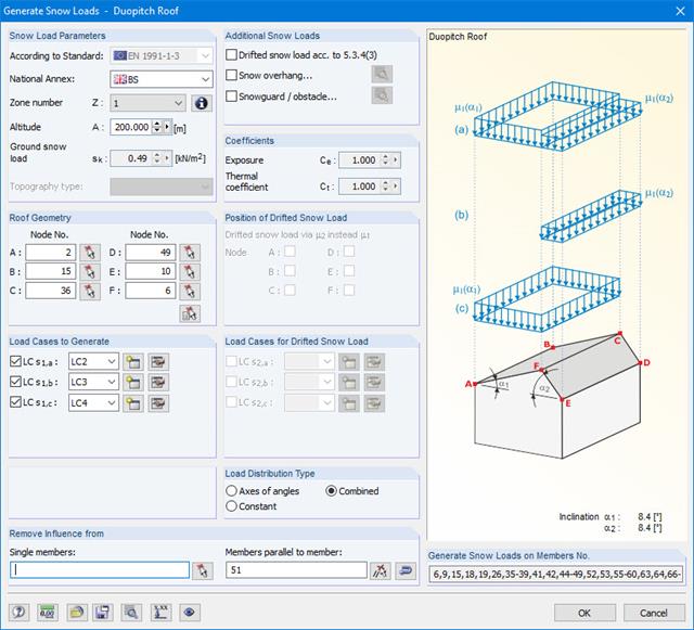
Snow loads can be generated as member loads on flat/monopitch roofs and duopitch roofs.
Additional snow loads such as drifted snow loads, snow overhangs, and snow guards can be taken into account as well.
The following standards are available:
-
EN 1991-1-3 (incl. National Annexes)
-
DIN 1055-5
-
CTE DB-SE-AE
-
ASCE/SEI 7-16
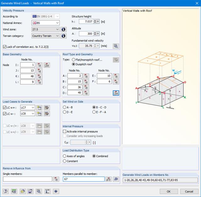
Wind loads can be automatically generated as member loads on the following structural components (optional with internal pressure for open buildings):
- Vertical walls
- Flat roofs
- Monopitch roofs
- Duopitch/troughed roofs
- Vertical walls with roof
The following standards are available:
-
EN 1991-1-3 (incl. National Annexes)
-
DIN 1055-4
-
CTE DB-SE-AE
-
ASCE/SEI 7-16

Wind loads can be automatically generated as member loads or area loads on the following structural components (optional with internal pressure for open buildings):
- Vertical walls
- Flat roofs
- Monopitch roofs
- Duopitch/troughed roofs
- Vertical walls with roof
The following standards are available:
-
EN 1991-1-3 (incl. National Annexes)
-
DIN 1055-4
-
CTE DB-SE-AE
-
ASCE/SEI 7-16