Program RFEM 6 do analizy statyczno-wytrzymałościowej jest podstawą systemu modułowego. Program główny RFEM 6 służy do definiowania konstrukcji, materiałów i obciążeń płaskich i przestrzennych układów konstrukcyjnych składających się z płyt, ścian, powłok i prętów. Program umożliwia również tworzenie konstrukcji mieszanych oraz modelowanie elementów bryłowych i kontaktowych.
RSTAB 9 to wydajne oprogramowanie do obliczeń konstrukcji szkieletowych 3D, odzwierciedlające aktualny stan wiedzy i pomagające inżynierom sprostać wymaganiom współczesnej inżynierii lądowej.
Często zbyt długo zajmujesz się obliczaniem przekrojów? Oprogramowanie firmy Dlubal i program samodzielny RSECTION ułatwiają pracę, określając i przeprowadzając analizę naprężeń dla różnych przekrojów.
Czy zawsze wiesz, skąd wieje wiatr? Oczywiście od strony innowacji! RWIND 3 to program, który wykorzystuje cyfrowy tunel aerodynamiczny do numerycznej symulacji przepływu wiatru. Program symuluje przepływ wokół dowolnej geometrii budynku i określa obciążenia wiatrem na powierzchnie.
Szukasz narzędzia do przeglądu stref obciążenia śniegiem, wiatrem i trzęsieniem ziemi? Dobrze trafiłeś! Skorzystaj z narzędzia do geolokalizacji do szybkiego i skutecznego definiowania obciążenia śniegiem, prędkości wiatru, obciążenia trzęsieniem ziemi, zgodnie z Eurokodem i innymi międzynarodowymi normami.
Chcesz wypróbować możliwości programów Dlubal Software? To Twoja szansa! Dzięki 90-dniowej pełnej wersji, możesz w pełni przetestować wszystkie nasze programy.
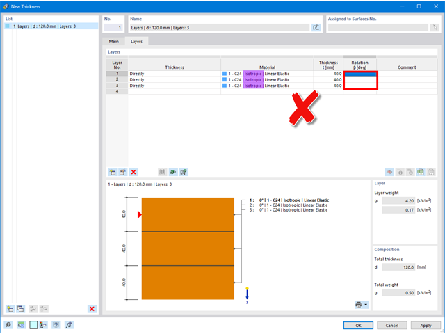
Jeżeli w kolumnie ' Obrót ' nie można zdefiniować kąta, to dla materiału wybrano izotropowy model materiałowy, w którym sztywności są identyczne we wszystkich kierunkach i nie ma potrzeby definiowania kąta.
W przypadku używania materiałów anizotropowych (np. drewno) należy upewnić się, że model materiału ' jest ortotropowy | Wybrano opcję Liniowa sprężystość (powierzchnie) '.
Uwaga: Model materiałowy ' ortotropowy | Drewno | Liniowe sprężyste (powierzchnie) 'obecnie nie mogą być stosowane w połączeniu z typem grubości ' Warstwy '.
Po przejściu na ortotropowy model materiałowy można odpowiednio obracać poszczególne warstwy.
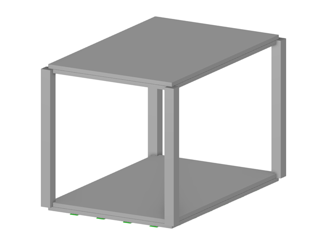
Masy można pominąć w ustawieniach analizy modalnej.
Możliwe jest pominięcie mas we wszystkich nieruchomych podporach węzłowych i podporach liniowych lub utworzenie wyboru z poszczególnych obiektów.
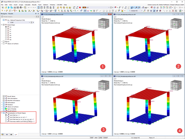
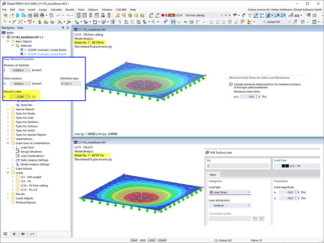
Bezpośrednio w nawigatorze Wyniki można dostosować wyświetlanie normalizacji postaci drgań własnych. W przypadku zmiany ustawienia nie jest konieczne ponowne obliczanie.
W zależności od ustawienia największe przemieszczenie lub odkształcenie stanowi wartość odniesienia 1, do której skalowane są pozostałe wyniki.
W przypadku obciążenia typu Analiza modalna można również zdefiniować zmiany konstrukcyjne. W ten sposób można uzyskać dostęp do modyfikacji sztywności poszczególnych obiektów, a w razie potrzeby również dezaktywować wybrane obiekty.
W ustawieniach analizy modalnej można ustawić minimalne odkształcenie osiowe dla kabli i membran, aby zastosować początkowe naprężenie wstępne dla obiektów, a tym samym poprawić zbieżność obliczeń. Wstępne naprężenie wstępne jest stosowane do obiektów w sposób uproszczony.
Porównując to ustawienie z obciążeniem powierzchniowym typu Odkształcenie osiowe, należy zwrócić uwagę na fakt, że te dwa podejścia różnią się od siebie. Przy obciążeniu powierzchniowym przeprowadza się obliczenia w taki sposób, że rzeczywiste naprężenie może odbiegać od zadanego. Obliczenia uwzględniają również inne warunki brzegowe, takie jak współczynnik Poissona materiału.
Można to łatwo sprawdzić, zmieniając współczynnik Poissona w materiale. Stosunek Poissona ' s różny od 0 oznacza, że odkształcenie w kierunku x i y powierzchni oddziałuje ze sobą, co nie prowadzi już do stałego naprężenia/odkształcenia na całej powierzchni.
Jeżeli współczynnik Poissona wynosi 0, można uzyskać takie same wyniki.
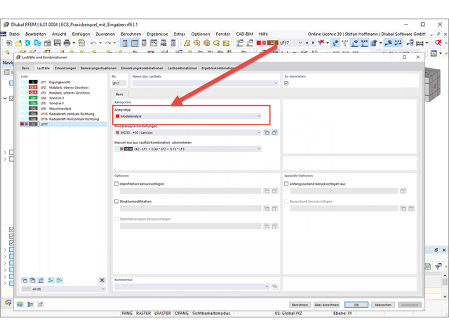
Aby wyświetlić kształty drgań własnych w analizie dynamicznej, należy utworzyć przypadek obciążenia typu Analiza modalna i określić w nim ustawienia dla analizy modalnej.
Po zakończeniu obliczeń można ocenić uzyskane wyniki w nawigatorze Wyniki. W tabeli można również znaleźć dalsze informacje.
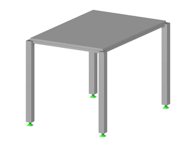
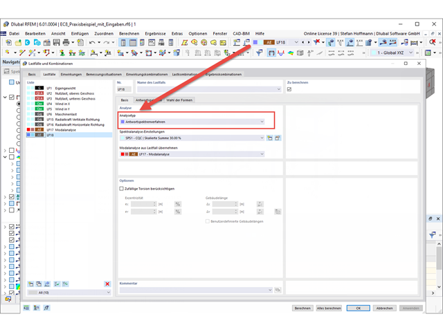
Aby przeprowadzić analizę trzęsienia ziemi, potrzebna jest analiza modalna, a następnie przypadek obciążenia typu Analiza spektrum odpowiedzi.
Po przeprowadzeniu analizy modalnej należy utworzyć nowy przypadek obciążenia. Tutaj znajdują się zwykłe ustawienia z poprzedniej generacji programu.
W zakładce Spektrum odpowiedzi można zdefiniować swoje spektrum odpowiedzi w zwykły sposób. Jeżeli chcesz użyć spektrum odpowiedzi zgodnie z normą, upewnij się, że w danych ogólnych normy II wybrano żądaną normę.
W zakładce Wybór trybów można wybrać kształty postaci i w razie potrzeby przefiltrować je.
Po obliczeniu przypadku obciążenia otrzymujemy wyniki.