Program RFEM 6 do analizy statyczno-wytrzymałościowej jest podstawą systemu modułowego. Program główny RFEM 6 służy do definiowania konstrukcji, materiałów i obciążeń płaskich i przestrzennych układów konstrukcyjnych składających się z płyt, ścian, powłok i prętów. Program umożliwia również tworzenie konstrukcji mieszanych oraz modelowanie elementów bryłowych i kontaktowych.
RSTAB 9 to wydajne oprogramowanie do obliczeń konstrukcji szkieletowych 3D, odzwierciedlające aktualny stan wiedzy i pomagające inżynierom sprostać wymaganiom współczesnej inżynierii lądowej.
Często zbyt długo zajmujesz się obliczaniem przekrojów? Oprogramowanie firmy Dlubal i program samodzielny RSECTION ułatwiają pracę, określając i przeprowadzając analizę naprężeń dla różnych przekrojów.
Czy zawsze wiesz, skąd wieje wiatr? Oczywiście od strony innowacji! RWIND 3 to program, który wykorzystuje cyfrowy tunel aerodynamiczny do numerycznej symulacji przepływu wiatru. Program symuluje przepływ wokół dowolnej geometrii budynku i określa obciążenia wiatrem na powierzchnie.
Szukasz narzędzia do przeglądu stref obciążenia śniegiem, wiatrem i trzęsieniem ziemi? Dobrze trafiłeś! Skorzystaj z narzędzia do geolokalizacji do szybkiego i skutecznego definiowania obciążenia śniegiem, prędkości wiatru, obciążenia trzęsieniem ziemi, zgodnie z Eurokodem i innymi międzynarodowymi normami.
Chcesz wypróbować możliwości programów Dlubal Software? To Twoja szansa! Dzięki 90-dniowej pełnej wersji, możesz w pełni przetestować wszystkie nasze programy.
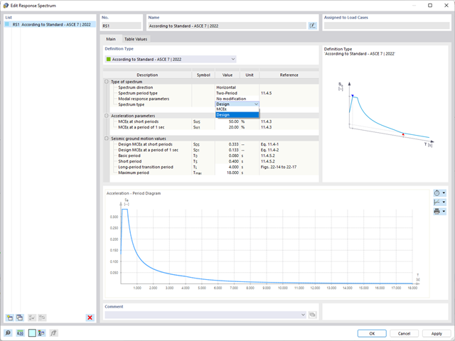
Norma ASCE 7-22 oferuje kilka typów widm obliczeniowych. W tym FAQ chcielibyśmy skoncentrować się na następujących dwóch widmach obliczeniowych:
Widmo dwuokresowe jest normalnie zapisywane w programie. Jednak na podstawie danych dostępnych w normie można zaproponować tylko horyzontalne spektrum obliczeniowe/widmo MCER oraz modyfikację związaną z siłą i przemieszczeniem.
Dla wielookresowego spektrum obliczeniowego określane są dyskretne wartości liczbowe. W normie ASCE 7-22 podano, że wartości te można sprawdzić na stronie geobazy USGS Seismic Design Geodatabase. W obecnym stanie rozwoju istnieje możliwość utworzenia zdefiniowanego przez użytkownika spektrum odpowiedzi ze współczynnikiem g (w zależności od -6/000369 stała konwersji masy ), aby wykorzystać dane np. z ASCE 7 Hazard Tool [1].
Proszę postępować w następujący sposób:
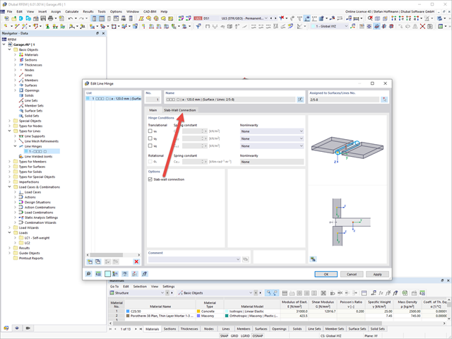
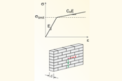
Rozszerzenie Masonry Design umożliwia automatyczne określenie sztywności przegubu ściany-płyty. Wykresy powstały w ramach projektu badawczego DDmaS - „Cyfryzacja obliczeń konstrukcji murowanych” i wywodzą się z normy.
Na linii połączenia obu powierzchni należy zdefiniować przegub liniowy i aktywować połączenie płyta-ściana.
W zakładce Połączenie płyta-ściana można teraz wprowadzić parametry. Następnie kliknij przycisk Regeneruj [...].
Następnie wyświetlane są wyznaczone wykresy.
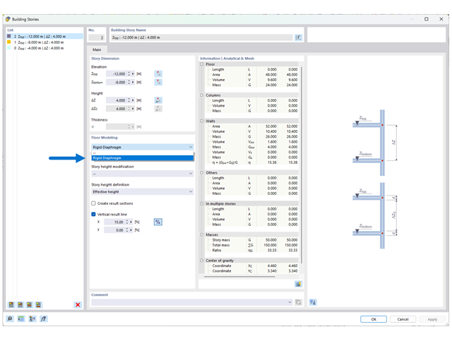
Rozszerzenie Model budynku i funkcja modelowania kondygnacji za pomocą "Tarczy sztywnej" nie mogą być stosowane we wszystkich typach budynków.
Funkcja została pierwotnie opracowana dla budynków 3D o 5-10 kondygnacjach (lub więcej) o regularnym lub tym samym rzucie. Oznacza to, że należy przypisać funkcję "Tarcza sztywna" tylko tym płytom, na których ściany i słupy są identycznie rozmieszczone w kondygnacji powyżej i poniżej. W przeciwnym razie może dojść do niestateczności.
Jeżeli model został wprowadzony poprawnie zgodnie z tą konwencją, pojawią się trzy opcje wyświetlania wyników:
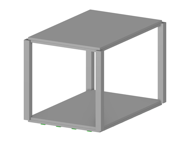
Wyświetlenie wyników po wybraniu opcji "Całkowita" ma na celu wyświetlenie wyników dla całych elementów pionowych (np. ścian, ścian usztywniających, słupów itp.). Patrz rysunek 02. W przypadku wybrania opcji "Tylko stropy" wyniki osobnych obliczeń płyt są wyświetlane jako model 2D. Opcja "Kombinacja" jest odpowiednio taka sama dla dwóch wyżej wymienionych typów wyników.
W przypadku mniejszych modeli 3D i budynków z różnymi planami pięter lepiej jest pracować ze zwykłym modelem 3D. W przypadku modeli, które czasami mają regularne rzuty, można alternatywnie przypisać opcję "Tarcza sztywna" do poszczególnych płyt stropowych. Geometria rzutu kondygnacji powyżej i poniżej tego stropu powinna być ponownie identyczna.
Podstawowe wyodrębnienie stropu 2D z dowolnego modelu 3D nie jest możliwe w przypadku technologii zaimplementowanej dla tej funkcji rozszerzenia.
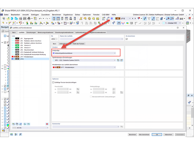
Aby przeprowadzić analizę trzęsienia ziemi, potrzebna jest analiza modalna, a następnie przypadek obciążenia typu Analiza spektrum odpowiedzi.
Po przeprowadzeniu analizy modalnej należy utworzyć nowy przypadek obciążenia. Tutaj znajdują się zwykłe ustawienia z poprzedniej generacji programu.
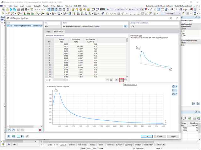
W zakładce Spektrum odpowiedzi można zdefiniować swoje spektrum odpowiedzi w zwykły sposób. Jeżeli chcesz użyć spektrum odpowiedzi zgodnie z normą, upewnij się, że w danych ogólnych normy II wybrano żądaną normę.
W zakładce Wybór trybów można wybrać kształty postaci i w razie potrzeby przefiltrować je.
Po obliczeniu przypadku obciążenia otrzymujemy wyniki.
Tak, można również eksportować spektrum odpowiedzi z programu RFEM 6 i importować je do programu RFEM 5 jako spektrum odpowiedzi zdefiniowane przez użytkownika. Należy pamiętać, że eksport i import za pomocą programu Excel również mogą mieć różne kolumny/opisy ze względu na różne wersje.
Eksportuj dane z programu RFEM 6 do Excela.
Jeśli zechcesz bezpośrednio zaimportować tę tabelę, otrzymasz komunikat o błędzie. W programie RFEM 5 przewidziano inny opis w arkuszu roboczym i tylko w dwóch kolumnach.
Po dostosowaniu nazwy w programie Excel i usunięciu kolumny z wynikami częstotliwości, będzie można edytować spektrum odpowiedzi w programie RFEM 5.
Masy można pominąć w ustawieniach analizy modalnej.
Możliwe jest pominięcie mas we wszystkich nieruchomych podporach węzłowych i podporach liniowych lub utworzenie wyboru z poszczególnych obiektów.
Tak, można kontrolować rozkład obciążenia, ustawiając naprężenia graniczne dla bardzo wysokiego lub małego rozciągania.