Program RFEM 6 do analizy statyczno-wytrzymałościowej jest podstawą systemu modułowego. Program główny RFEM 6 służy do definiowania konstrukcji, materiałów i obciążeń płaskich i przestrzennych układów konstrukcyjnych składających się z płyt, ścian, powłok i prętów. Program umożliwia również tworzenie konstrukcji mieszanych oraz modelowanie elementów bryłowych i kontaktowych.
RSTAB 9 to wydajne oprogramowanie do obliczeń konstrukcji szkieletowych 3D, odzwierciedlające aktualny stan wiedzy i pomagające inżynierom sprostać wymaganiom współczesnej inżynierii lądowej.
Często zbyt długo zajmujesz się obliczaniem przekrojów? Oprogramowanie firmy Dlubal i program samodzielny RSECTION ułatwiają pracę, określając i przeprowadzając analizę naprężeń dla różnych przekrojów.
Czy zawsze wiesz, skąd wieje wiatr? Oczywiście od strony innowacji! RWIND 3 to program, który wykorzystuje cyfrowy tunel aerodynamiczny do numerycznej symulacji przepływu wiatru. Program symuluje przepływ wokół dowolnej geometrii budynku i określa obciążenia wiatrem na powierzchnie.
Szukasz narzędzia do przeglądu stref obciążenia śniegiem, wiatrem i trzęsieniem ziemi? Dobrze trafiłeś! Skorzystaj z narzędzia do geolokalizacji do szybkiego i skutecznego definiowania obciążenia śniegiem, prędkości wiatru, obciążenia trzęsieniem ziemi, zgodnie z Eurokodem i innymi międzynarodowymi normami.
Chcesz wypróbować możliwości programów Dlubal Software? To Twoja szansa! Dzięki 90-dniowej pełnej wersji, możesz w pełni przetestować wszystkie nasze programy.
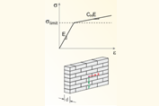
Tak, można kontrolować rozkład obciążenia, ustawiając naprężenia graniczne dla bardzo wysokiego lub małego rozciągania.
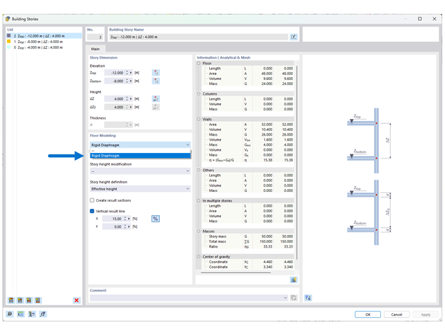
Rozszerzenie Model budynku i funkcja modelowania kondygnacji za pomocą "Tarczy sztywnej" nie mogą być stosowane we wszystkich typach budynków.
Funkcja została pierwotnie opracowana dla budynków 3D o 5-10 kondygnacjach (lub więcej) o regularnym lub tym samym rzucie. Oznacza to, że należy przypisać funkcję "Tarcza sztywna" tylko tym płytom, na których ściany i słupy są identycznie rozmieszczone w kondygnacji powyżej i poniżej. W przeciwnym razie może dojść do niestateczności.
Jeżeli model został wprowadzony poprawnie zgodnie z tą konwencją, pojawią się trzy opcje wyświetlania wyników:
Wyświetlenie wyników po wybraniu opcji "Całkowita" ma na celu wyświetlenie wyników dla całych elementów pionowych (np. ścian, ścian usztywniających, słupów itp.). Patrz rysunek 02. W przypadku wybrania opcji "Tylko stropy" wyniki osobnych obliczeń płyt są wyświetlane jako model 2D. Opcja "Kombinacja" jest odpowiednio taka sama dla dwóch wyżej wymienionych typów wyników.
W przypadku mniejszych modeli 3D i budynków z różnymi planami pięter lepiej jest pracować ze zwykłym modelem 3D. W przypadku modeli, które czasami mają regularne rzuty, można alternatywnie przypisać opcję "Tarcza sztywna" do poszczególnych płyt stropowych. Geometria rzutu kondygnacji powyżej i poniżej tego stropu powinna być ponownie identyczna.
Podstawowe wyodrębnienie stropu 2D z dowolnego modelu 3D nie jest możliwe w przypadku technologii zaimplementowanej dla tej funkcji rozszerzenia.
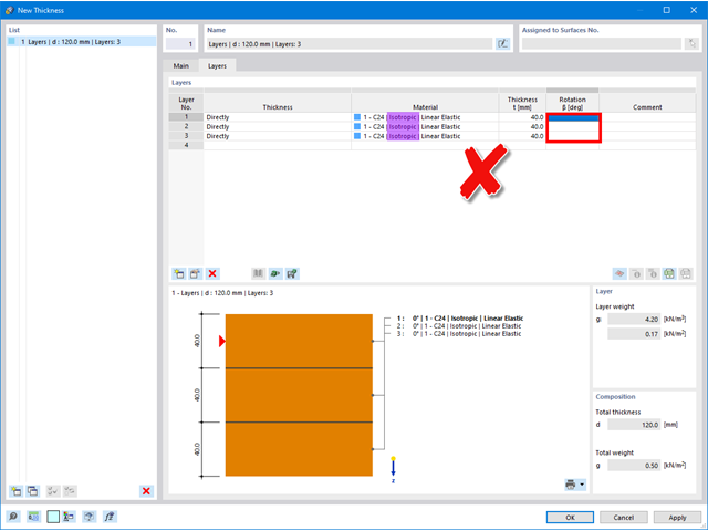
Jeżeli w kolumnie ' Obrót ' nie można zdefiniować kąta, to dla materiału wybrano izotropowy model materiałowy, w którym sztywności są identyczne we wszystkich kierunkach i nie ma potrzeby definiowania kąta.
W przypadku używania materiałów anizotropowych (np. drewno) należy upewnić się, że model materiału ' jest ortotropowy | Wybrano opcję Liniowa sprężystość (powierzchnie) '.
Uwaga: Model materiałowy ' ortotropowy | Drewno | Liniowe sprężyste (powierzchnie) 'obecnie nie mogą być stosowane w połączeniu z typem grubości ' Warstwy '.
Po przejściu na ortotropowy model materiałowy można odpowiednio obracać poszczególne warstwy.
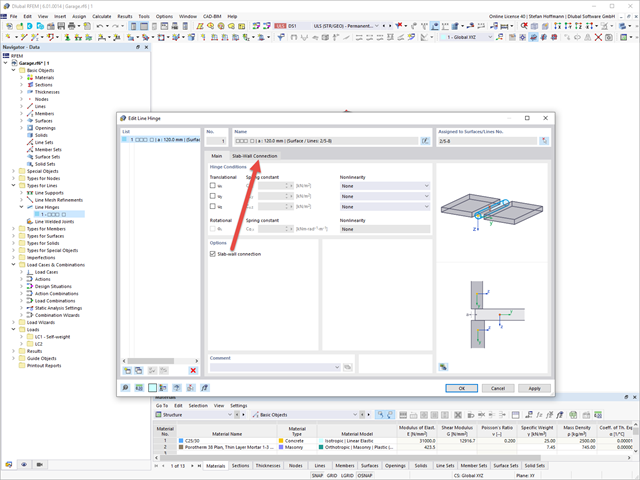
Rozszerzenie Masonry Design umożliwia automatyczne określenie sztywności przegubu ściany-płyty. Wykresy powstały w ramach projektu badawczego DDmaS - „Cyfryzacja obliczeń konstrukcji murowanych” i wywodzą się z normy.
Na linii połączenia obu powierzchni należy zdefiniować przegub liniowy i aktywować połączenie płyta-ściana.
W zakładce Połączenie płyta-ściana można teraz wprowadzić parametry. Następnie kliknij przycisk Regeneruj [...].
Następnie wyświetlane są wyznaczone wykresy.