12 Wyniki
Wyświetl wyniki:
Sortuj według:

Wymiarowanie prętów stalowych formowanych na zimno zgodnie z AISI S100-16/CSA S136-16 jest dostępne w RFEM 6. Dostęp do obliczeń można uzyskać, wybierając normy „AISC 360” lub „CSA S16” w rozszerzeniu Projektowanie konstrukcji stalowych. Następnie dla obliczeń elementów formowanych na zimno automatycznie wybierane jest „AISI S100” lub „CSA S136”.
Do obliczania sprężystego obciążenia wyboczeniowego pręta program RFEM stosuje metodę DSM. Bezpośrednia metoda wytrzymałości oferuje dwa typy rozwiązań, numeryczne (metoda pasm skończonych) i analityczne (specyfikacja). Krzywą charakterystyczną (sygnaturę) FSM i kształty wyboczenia można wyświetlić w oknie dialogowym Przekroje.
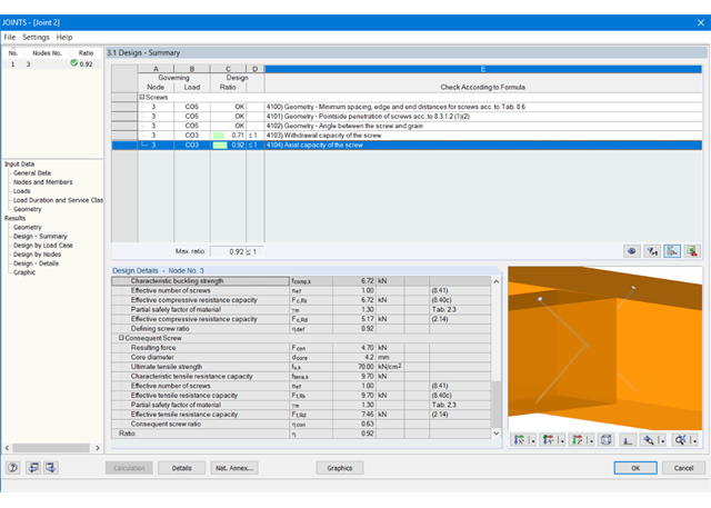
Główne funkcje wymiarowania połączeń są najpierw pogrupowane i wyświetlane wraz z podstawową geometrią połączenia w pierwszym oknie wyników. W kolejnych oknach wyników można zobaczyć wszystkie istotne szczegóły obliczeń.
Wymiary, właściwości materiału i spoiny istotne dla konstrukcji połączenia są wyświetlane natychmiast i można je wydrukować. Podobnie aktywowany jest eksport do pliku DXF. Połączenia można zwizualizować w module RF-/JOINTS Timber - Timber to Timber oraz w programie RFEM/RSTAB.
Wszystkie grafiki mogą zostać dołączone do protokołu wydruku programu RFEM/RSTAB lub wydrukowane bezpośrednio. Dzięki skalowaniu wyników, możliwa jest optymalna kontrola wizualna już na etapie projektowania.
Moduł wyświetla następujące wyniki:
- Minimalna odległość między trzpieniami
- Nośność każdego wkręta
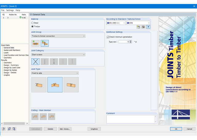
Najpierw należy wybrać typ połączenia i normę obliczeniową.
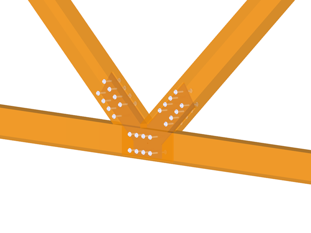
Połączone pręty są importowane z modelu w programie RFEM/RSTAB. Moduł dodatkowy automatycznie sprawdza, czy wszystkie warunki geometrii są spełnione.
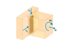
Ponadto obciążenia są importowane automatycznie z programu RFEM/RSTAB. W oknie Geometria można określić parametry wkręta (średnica, długość, kąt itp.).
.png?mw=640&hash=c1087880acc023575381bb136280b0c348568350)
- Obliczanie połączeń przegubowych
- Nachylenie dwuosiowe połączonego pręta (np. połączenie krokwi)
- Połączenie dowolnej liczby prętów na jednym węźle dla typu "Tylko pręt główny"
- Średnica wkręta 6 mm - 12 mm
- Automatyczne sprawdzanie minimalnego rozstawu wkrętów
- Optymalne definiowanie rozstawu wkrętów
- Przenoszenie mimośrodu z RFEM/RSTAB
- Poprzeczne lub równoległe rozmieszczenie wkrętów
- Zdefiniowanie do 16 wkrętów w rzędzie
- Graficzne przedstawienie połączeń w module dodatkowym i w RFEM/RSTAB
- Możliwość przeprowadzenia wszystkich wymaganych obliczeń
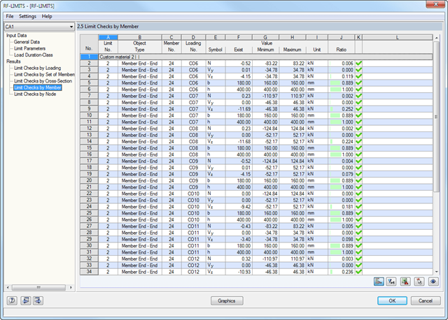
Najpierw wyświetlane są decydujące obliczenia połączenia dla danego przypadku obciążenia oraz kombinacji obciążeń lub kombinacji wyników. Ponadto możliwe jest oddzielne wyświetlanie wyników dla zbiorów prętów, przekrojów, prętów, węzłów i podpór węzłowych.
- Możesz użyć filtra, aby jeszcze bardziej zredukować wyświetlane wyniki, a tym samym przedstawić je w bardziej przejrzysty sposób.
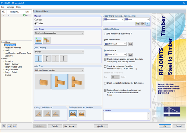
Najpierw należy wybrać typ połączenia, normę obliczeniową oraz materiał stalowej płyty i kołka. Aby przeprowadzić obliczenia zgodnie z EN 1995-1-1, można wybrać system sworzni SFS intec WS‑T. W takim przypadku odpowiedni materiał jest wstępnie ustawiony zgodnie z aprobatą techniczną producenta.
Połączone pręty są następnie importowane z modelu programów RFEM/RSTAB. Moduł dodatkowy automatycznie sprawdza, czy wszystkie warunki geometrii są spełnione. Alternatywnie, połączenie można zdefiniować ręcznie.
- Obciążenie jest również importowane z programu RFEM/RSTAB lub, w przypadku ręcznej definicji połączenia, wprowadzane są obciążenia. W oknie Geometria wyświetlane są wymiary płyty stalowej oraz rozmieszczenie łączników.
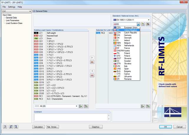
Po wybraniu obciążeń wymaganych do obliczeń oraz, w razie potrzeby, żądanej normy do obliczeń, w oknie 1.2 Parametry graniczne można zdefiniować obciążenia graniczne. Możliwe jest dodawanie innych producentów do listy w bazie danych.
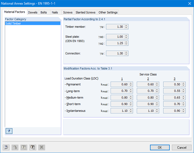
Po wybraniu wszystkich elementów granicznych do obliczeń można opcjonalnie zdefiniować klasę trwania obciążenia (KTO). Trzecie okno modułu jest dostępne jedynie w przypadku wymiarowania elementów połączeń drewnianych wg EN 1995-1-1 lub DIN 1052.
Po obliczeniach, moduł dodatkowy RF-/JOINTS Timber-Steel to Timber pokazuje sztywność połączenia dla wszystkich poszczególnych prętów. Moduł wyświetla następujące wyniki:
- Minimalna odległość między trzpieniami
- Nośność pojedynczego łącznika
- Blachy (nośność i naprężenia wg Eurokodu 3 i AISC)
- Analiza naprężeń wraz z redukcją przekrojów drewnianych
- zniszczenie przy ścinaniu blokowym
- Całkowita nośność (w tym określenie sztywności, rozciąganie poprzeczne zgodnie z EC 5 i inne)
- Obliczenia odporności ogniowej zgodnie z EN 1995-1-2
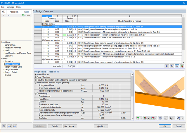
Główne wyniki wymiarowania połączenia są podzielone w grupach i przedstawiane w tabeli razem z geometrą połączenia. W kolejnych oknach wyników można zobaczyć wszystkie istotne szczegóły obliczeń.
Jednocześnie wyświetlane są także wymiary, właściwości materiałów i spoin istotnych dla konstrukcji połączenia, wszystkie dane mogą zostać uwzględnione w protokole wydruku. Podobnie aktywowany jest eksport do pliku DXF. Połączenia można zwizualizować w module RF-/JOINTS Timber - Steel to Timber lub w modelu RFEM/RSTAB.
Wszystkie grafiki można zintegrować w protokole wydruku programu RFEM/RSTAB lub wydrukować je bezpośrednio. Dzięki skalowaniu wyników, możliwa jest optymalna kontrola wizualna już na etapie projektowania.
- Projektowanie połączeń przegubowych, nośnych i półsztywnych
- Definicja do 5 stalowych płyt przekrojowych w belkach drewnianych
- Do 8 prętów połączonych z jednym węzłem
- Grubość płyty stalowej 5 mm – 40 mm
- Wszystkie rozmiary łączników
- Automatyczne sprawdzanie minimalnej odległości między łącznikami
- Opcjonalne dowolne definiowanie rozstawu łączników
- Definiowanie niesymetrycznych układów łączników (np. dowolnych łańcuchów wielokątnych)
- Graficzne przedstawienie połączeń w module dodatkowym i w RFEM/RSTAB
- Wszystkie wymagane obliczenia stali i drewna, w tym redukcja wartości przekrojów
- Wymiarowanie poprzecznego zbrojenia rozciąganego (tylko dla EN 1995-1-1)
- Eksport do RFEM/RSTAB mimośrodów prętów, które zostaną uwzględnione przy wyznaczaniu sił wewnętrznych
- Długość sworznia opcjonalnie mniejsza niż szerokość przekroju (dla kołków drewnianych)
- Eksport DXF geometrii połączenia
- Obliczenia odporności ogniowej zgodnie z EN 1995-1-2
- Wymiarowanie końców, prętów, podpór węzłowych, węzłów i powierzchni
- Uwzględnienie określonych obszarów obliczeniowych
- Kontrola wymiarów przekroju
- Wymiarowanie według EN 1995-1-1 (Europejska norma dotycząca drewna) zgodnie z odpowiednimi załącznikami krajowymi + DIN 1052 + DSTV DIN EN 1993-1-8 + ANSI/AWC - NDS 2015 (norma amerykańska)
- Projektowanie różnych materiałów, takich jak stal, beton i inne
- Nie ma konieczności łączenia się z konkretnymi normami
- Rozszerzalna biblioteka o elementy łaczące z drewna (SIHGA, Sherpa, WÜRTH, Simpson StrongTie, KNAPP, PITZL) i elementy stalowe (połączenia znormalizowane w konstrukcjach stalowych zgodnie z EC 3, M-connect, PFEIFER, TG-Technik)
- Nośności graniczne belek drewnianych firm STEICO i Metsä Wood dostępne w bibliotece
- Połączenie z MS Excel
- Optymalizacja elementów łączących (obliczany jest element najczęściej wykorzystywany)