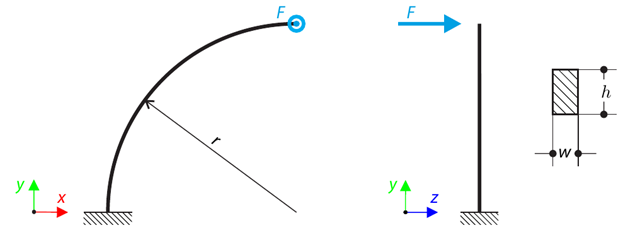
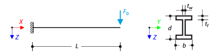
A quarter-circle beam with a rectangular cross-section is loaded by means of an out-of-plane force. This force causes a bending moment, torsional moment, and transverse force. Stanovíme celkový průhyb zakřiveného nosníku bez zohlednění vlastní tíhy.
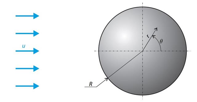
A sphere is subjected to a uniform flow of viscous fluid. The velocity of the fluid is considered at infinity. The goal is to determine the drag force. The parameters of the problem are set so that the Reynolds number is small and the radius of the sphere is also small, thus the theoretical solution can be reached - Stokes flow (G. G. Stokes 1851).
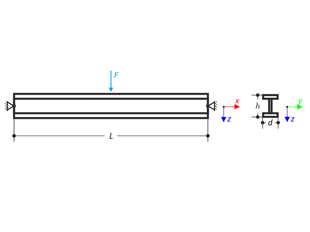
Nosník uložený na obou koncích je zatížen soustředěnou silou uprostřed. Neglecting its self-weight and shear stiffness, determine the beam's maximum deflection, normal force, and moment at the mid-span, assuming the second- and third-order analysis.
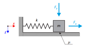
Jednoduchý oscilátor se skládá z tělesa o hmotnosti m (uvažuje se pouze ve směru osy x) a lineární pružiny s tuhostí k . The mass is embedded on a surface with Coulomb friction and is loaded by constant-in-time axial and transverse forces.
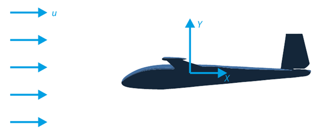
Cílem tohoto verifikačního příkladu je analyzovat proudění okolo kluzáku. Úkolem je stanovit součinitele odporu vzduchu a součinitele vztlaku vzhledem k úhlu náběhu. Pro tyto součinitele lze také vykreslit aerodynamickou poláru. Z pole rychlostí lze také určit mezní úhel laminárního proudění okolo profilu křídla. V programu RWIND 2 se použije dostupný 3D CAD model (soubor STL).
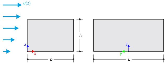
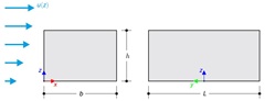
Verifikační příklad porovnává výpočet zatížení větrem na budovu s plochou střechou podle normy EN 1991-1-4 a pomocí CFD simulace v programu RWIND Simulation. The building is defined according to the sketch, and the inflow velocity profile is taken according to the standard EN 1991-1-4.
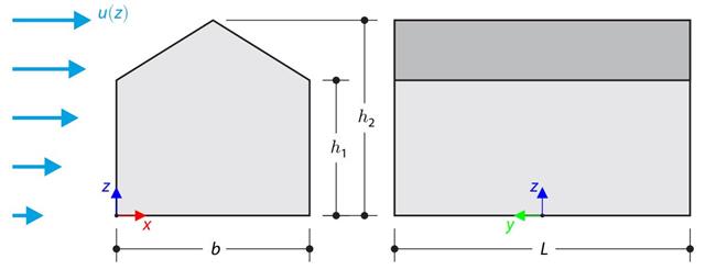
Verifikační příklad porovnává výpočet zatížení větrem na budovu se sedlovou střechou podle normy EN 1991-1-4 a pomocí CFD simulace v programu RWIND Simulation. The building is defined according to the sketch, and the inflow velocity profile is taken according to the standard EN 1991-1-4.
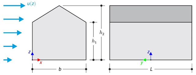
This verification example compares wind load calculations on a duopitch roof building using the ASCE 7-16 standard and using CFD simulation in RWIND Simulation. Budova je zadána v souladu s náčrtem. Rychlostní profil proudění vzduchu byl definován podle normy ASCE 7-16.
Japonský architektonický institut (AIJ) představil řadu známých srovnávacích scénářů simulace větru.
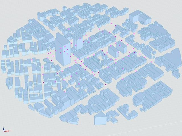
V následujícím příspěvku se budeme zabývat případem E - komplex budov ve skutečné městské oblasti s hustou koncentrací nízkopodlažních budov ve městě Niigata.
V následujícím textu je popsaný scénář simulován v programu RWIND2 a výsledky jsou porovnány se simulovanými a experimentálními výsledky AIJ.
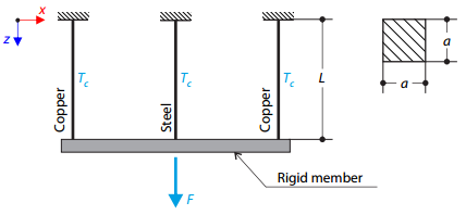
A truss structure consists of three rods (one steel and two copper) joined by a rigid member. The structure is loaded by a concentrated force and a temperature difference. Celkový průhyb konstrukce je stanoven bez zohlednění vlastní tíhy.
Japonský architektonický institut (AIJ) představil řadu známých srovnávacích scénářů simulace větru.
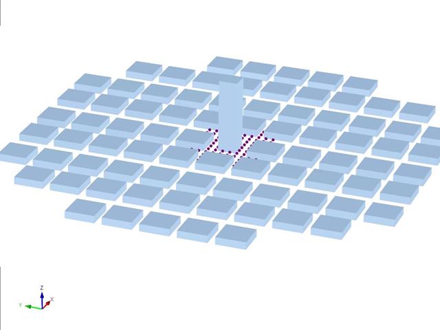
Následující článek se zabývá případem D - Výšková budova mezi městskými bloky.
V následujícím textu je popsaný scénář simulován v programu RWIND2 a výsledky jsou porovnány se simulovanými a experimentálními výsledky AIJ.
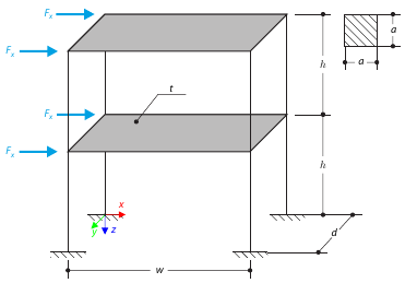
Tento příklad slouží jako ukázka vazby diafragma. The application is shown on a two-story structure. The structure is loaded by means of lateral forces according to Figure 1. Determine the maximum deflection of the structure ux in the direction of the loading forces using both the diaphragm constraint and the plate model of the floor.
This verification example compares wind load calculations on a flat roof building using the ASCE 7-16 standard and using CFD simulation in RWIND Simulation. Budova je zadána v souladu s náčrtem. Rychlostní profil proudění vzduchu byl definován podle normy ASCE 7-16.
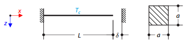
Ocelový prut mezi dvěma tuhými podporami se spárou na jednom konci je zatížen rozdílem teplot. While neglecting self‑weight, determine the total deformation of the rod and its internal axial force.
Nosník je na levém konci zcela upevněn (deplanace je omezena) a na pravém konci je podepřen vidlicovou podporou (deplanace je povolena). The beam is subjected to a torque, longitudinal force, and transverse force. Determine the behavior of the primary torsional moment, secondary torsional moment, and warping moment. The verification example is based on the example introduced by Gensichen and Lumpe.
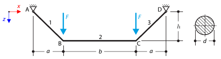
Lano je v počáteční poloze namáháno dvěma osamělými silami. The self‑weight is neglected. Determine the normal forces in the cable.
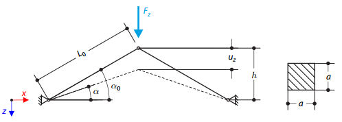
Konstrukce se skládá ze dvou nosníků, které jsou uloženy na kloubových podporách. The structure is loaded by concentrated force. The self-weight is neglected. Determine the relationship between the loading force and the deflection, considering large deformations.
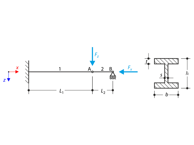
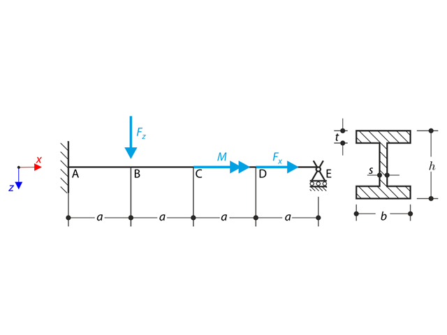
A structure made of an I-profile is fully fixed on the left end and embedded into the sliding support on the right end. Konstrukce se skládá ze dvou segmentů. The self-weight is neglected in this example. Determine the maximum deflection of the structure, the bending moment on the fixed end, the rotation of segment 2, and the reaction force at point B by means of the geometrically linear analysis and the second-order analysis. The verification example is based on the example introduced by Gensichen and Lumpe.
Časová analýza konzoly (SDOF - systém s jedním stupněm volnosti), která je buzena periodickou funkcí. Vertical deformations and accelerations calculated with direct integration and modal analysis in RF‑/DYNAM Pro - Forced Vibrations are compared with the analytical solution.
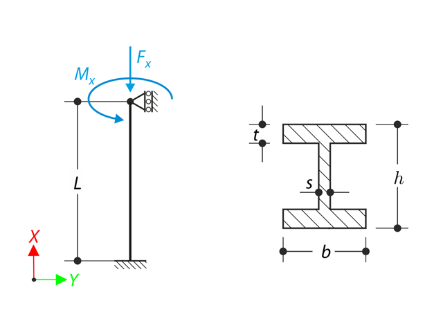
A member with the given boundary conditions is loaded by torsional moment and axial force. Neglecting its self-weight, determine the beam's maximum torsional deformation as well as its inner torsional moment, defined as the sum of a primary torsional moment and torsional moment caused by the normal force. Tyto hodnoty porovnáme při zohlednění nebo zanedbání vlivu normálové síly. The verification example is based on the example introduced by Gensichen and Lumpe.