Japonský architektonický institut (AIJ) představil řadu známých srovnávacích scénářů simulace větru.
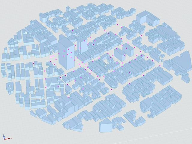
V následujícím příspěvku se budeme zabývat případem E - komplex budov ve skutečné městské oblasti s hustou koncentrací nízkopodlažních budov ve městě Niigata.
V následujícím textu je popsaný scénář simulován v programu RWIND2 a výsledky jsou porovnány se simulovanými a experimentálními výsledky AIJ.
Japonský architektonický institut (AIJ) v souladu se srovnávacími testy pro Windsimulation vorgestellt.
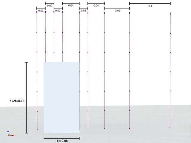
Podle nového návrhu "Případ A - výšková budova ve tvaru 2:1:1".
Im Folgenden wird das beschriebene Szenario in RWIND2 nachgebildet and die Ergebnisse se simulierten and der experimentellen Resultate des AIJ verglichen.
Japonský architektonický institut (AIJ) představil řadu známých srovnávacích scénářů simulace větru.
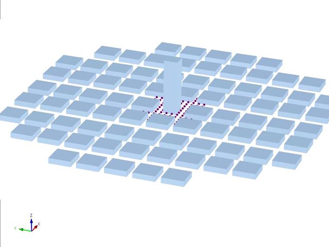
Následující článek se zabývá případem D - Výšková budova mezi městskými bloky.
V následujícím textu je popsaný scénář simulován v programu RWIND2 a výsledky jsou porovnány se simulovanými a experimentálními výsledky AIJ.
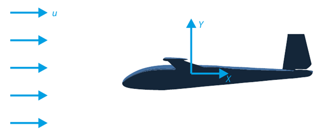
Cílem tohoto verifikačního příkladu je analyzovat proudění okolo kluzáku. Úkolem je stanovit součinitele odporu vzduchu a součinitele vztlaku vzhledem k úhlu náběhu. Pro tyto součinitele lze také vykreslit aerodynamickou poláru. Z pole rychlostí lze také určit mezní úhel laminárního proudění okolo profilu křídla. V programu RWIND 2 se použije dostupný 3D CAD model (soubor STL).
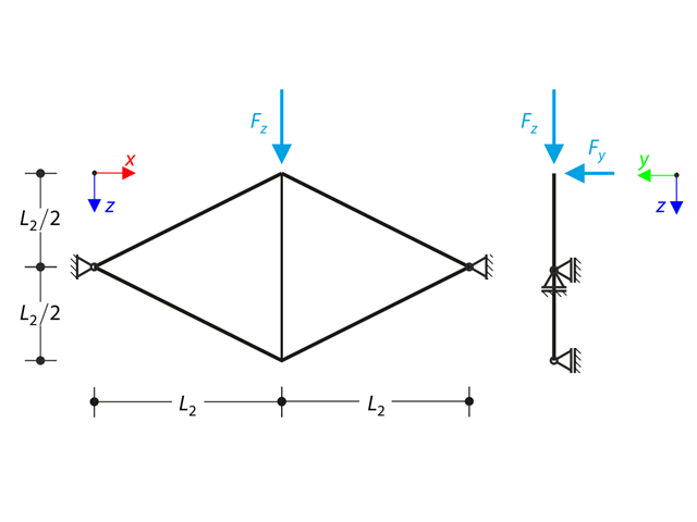
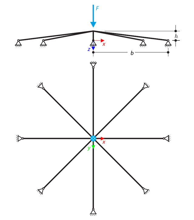
Rovinný příhradový vazník, který se skládá ze čtyř šikmých prutů a jednoho svislého prutu, je zatížen v horním uzlu svislou silou a silou mimo rovinu. Assuming the large deformation analysis and neglecting the self-weight, determine the normal forces of the members and the out-of-plane displacement of the upper node.
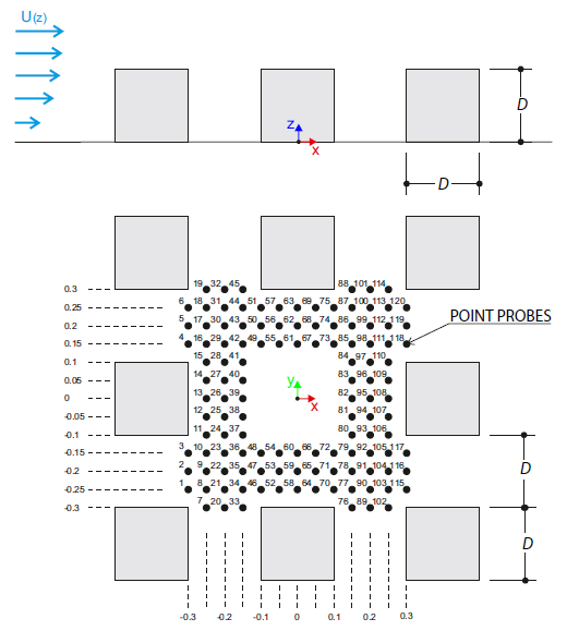
Verifikační příklad popisuje zatížení větrem v několika směrech proudění větru na modelu skupiny budov. The model consists of eight cubes. The velocity fields obtained by the RWIND simulation are compared with the measured values from the experiment. The experimental data are measured using a thermistor anemometer in the wind tunnel.
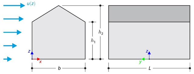
This verification example compares wind load calculations on a duopitch roof building using the ASCE 7-16 standard and using CFD simulation in RWIND Simulation. Budova je zadána v souladu s náčrtem. Rychlostní profil proudění vzduchu byl definován podle normy ASCE 7-16.
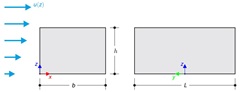
This verification example compares wind load calculations on a flat roof building using the ASCE 7-16 standard and using CFD simulation in RWIND Simulation. Budova je zadána v souladu s náčrtem. Rychlostní profil proudění vzduchu byl definován podle normy ASCE 7-16.
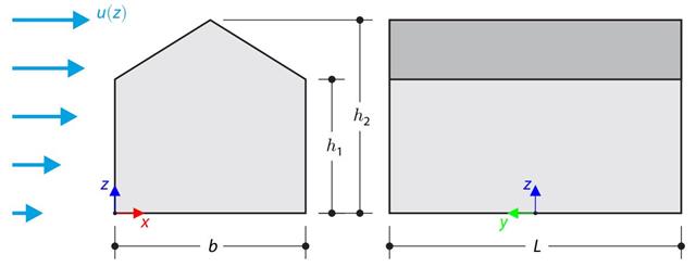
Verifikační příklad porovnává výpočet zatížení větrem na budovu se sedlovou střechou podle normy EN 1991-1-4 a pomocí CFD simulace v programu RWIND Simulation. The building is defined according to the sketch, and the inflow velocity profile is taken according to the standard EN 1991-1-4.
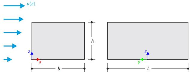
Verifikační příklad porovnává výpočet zatížení větrem na budovu s plochou střechou podle normy EN 1991-1-4 a pomocí CFD simulace v programu RWIND Simulation. The building is defined according to the sketch, and the inflow velocity profile is taken according to the standard EN 1991-1-4.
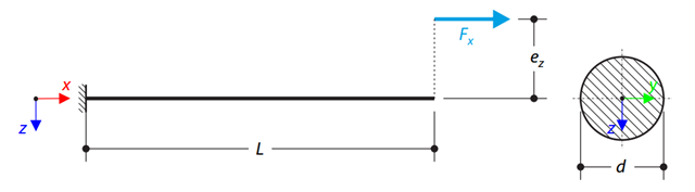
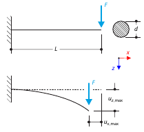
Konzola z kruhového prutu je zatížena excentrickou normálovou silou. Determine the maximum vertical deflection of the console using the geometrically linear and second-order analysis.
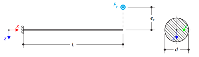
Konzola z kruhového prutu je zatížena excentrickou příčnou silou. Determine the maximum deflection and maximum twist of the console using the geometrically linear analysis.
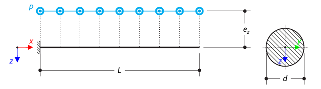
Konzola z kruhového prutu je zatížena excentrickým rovnoměrným zatížením. Determine the maximum deflection and maximum twist of the console using the geometrically linear analysis.
A symmetrical shallow structure is made of eight equal truss members, which are embedded into hinge supports. The structure is loaded by a concentrated force and alternatively by imposed nodal deformation over the critical limit point when the snap-through occurs. Imposed nodal deformation is used in RFEM 5 and RSTAB 8 to obtain the full equilibrium path of the snap-through. Vlastní tíha se v tomto příkladu nezohledňuje. Determine the relationship between the actual loading force and the deflection, considering large deformation analysis. Evaluate the load factor at the given deflections.
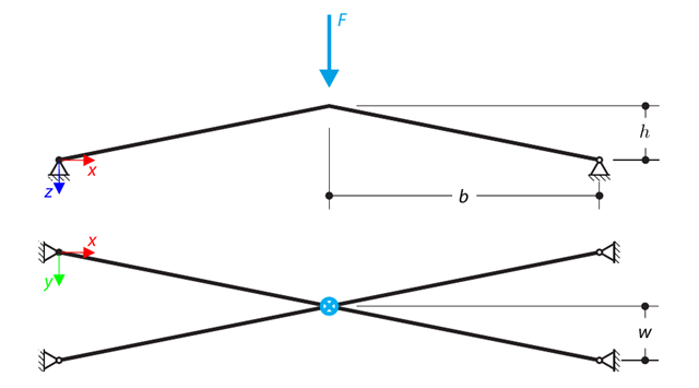
Konstrukce se skládá ze čtyř prutů, které jsou uloženy na kloubových podporách. The structure is loaded by a concentrated force and alternatively by imposed nodal deformation over the critical limit point, when snap-through occurs. Imposed nodal deformation is used in RFEM 5 and RSTAB 8 to obtain the full equilibrium path of the snap-through. The self-weight is neglected in this example. Determine the relationship between the actual loading force and the deflection, considering large deformation analysis. Evaluate the load factor at given deflections.
Konzola je na svém volném konci zatížena osamělou silou. Determine the maximum deflection of the console using large deformation analysis.
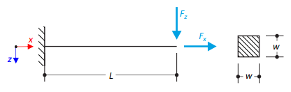
Konzola je na pravém konci zatížena příčnou a normálovou silou a na levém konci je plně fixována. The problem is described by the following set of parameters. The problem is solved by using the geometrically linear analysis, second-order analysis, and large deformation analysis.
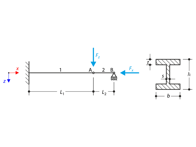
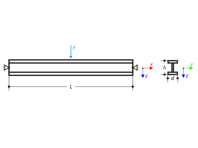
A structure made of an I-profile is fully fixed on the left end and embedded into the sliding support on the right end. Konstrukce se skládá ze dvou segmentů. The self-weight is neglected in this example. Determine the maximum deflection of the structure, the bending moment on the fixed end, the rotation of segment 2, and the reaction force at point B by means of the geometrically linear analysis and the second-order analysis. The verification example is based on the example introduced by Gensichen and Lumpe.
Konzola je na svém volném konci zatížena momentem. Using the geometrically linear analysis and large deformation analysis, and neglecting the beam's self-weight, determine the maximum deflections at the free end. The verification example is based on the example introduced by Gensichen and Lumpe.
Časová analýza konzoly (SDOF - systém s jedním stupněm volnosti), která je buzena periodickou funkcí. Vertical deformations and accelerations calculated with direct integration and modal analysis in RF‑/DYNAM Pro - Forced Vibrations are compared with the analytical solution.
Ocelové lano nebo membrána s kolíky na obou koncích jsou zatíženy rovnoměrným zatížením. Neglecting its self-weight, determine the maximum deflection of the structure using the large deformation analysis.
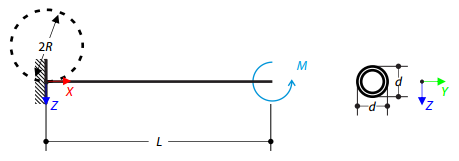
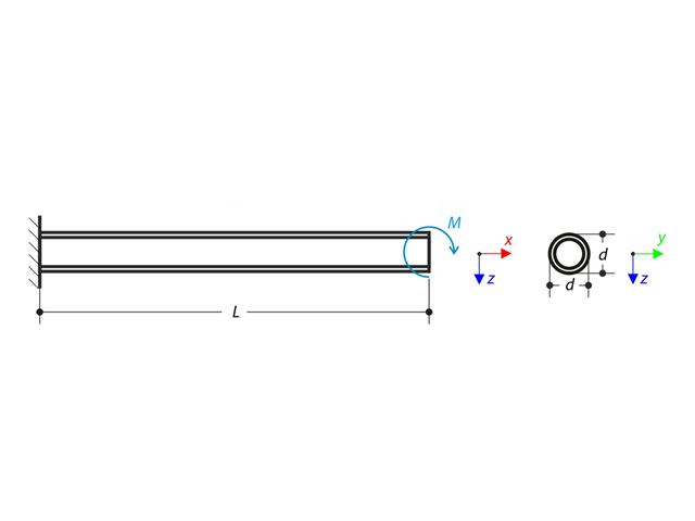
Stanovíme ohybový moment, který při působení na volném konci konzoly způsobí ohyb prutu do kruhového tvaru. Neglecting the beam's self-weight, assuming the large deformation analysis, and loading the cantilever with the moment, determine its maximum deflections.
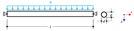
Nosník uložený na obou koncích je zatížen soustředěnou silou uprostřed. Neglecting its self-weight and shear stiffness, determine the beam's maximum deflection, normal force, and moment at the mid-span, assuming the second- and third-order analysis.
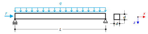
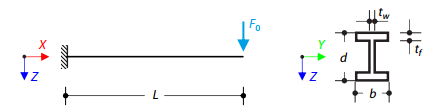
Ocelový nosník se čtvercovým průřezem je zatížen normálovou silou a spojitým zatížením. The image shows the calculation of the maximum bending deflection and critical load factor according to the second-order analysis.
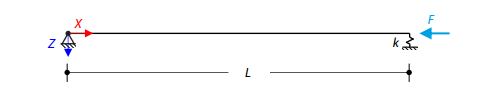
Osově zatížený ocelový nosník se čtvercovým průřezem je na jednom konci kloubově uložený a na druhém pružně podepřený. Two cases with different spring stiffnesses are considered. The verification example solves the calculation of the load factors of the beam in the image using the linear stability analysis.