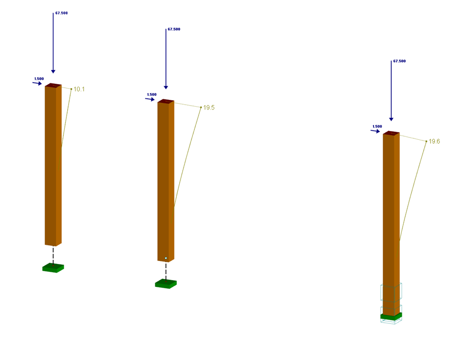
Timber Connection with Considering Elastic Slip Modulus
Model to Download
Description
This model was used to show how the rotational spring stiffness resulting from the connection is taken into account for a timber connection.
Model Used in
Keywords
Timber connection Connection Flexibility Rotational spring stiffness Slip modulus
Links
- Useful Tools for Fast Generation of Structures in RFEM
- Useful Tools for Fast Generation of Structures in RSTAB
Write Comment...
Write Comment...
Disclaimer

New
Considering Elastic Slip Modulus of Timber Connection
If a timber connection is designed as shown in Figure 01, the torsional spring stiffness resulting from the connection can be considered. This can be determined by using the modulus of displacement of the fastener and the polar moment of inertia of the connection, neglecting the area of the fastener.

The cross-section resistance design analyzes tension and compression along the grain, bending, bending and tension/compression as well as the strength in shear due to shear force.
The design of structural components at risk of buckling or lateral-torsional buckling is performed according to the Equivalent Member Method and considers the systematic axial compression, bending with and without compressive force as well as bending and tension. Deflection of inner spans and cantilevers is compared to the maximal allowable deflection.
Separate design cases allow for a flexible and stability analysis of members, sets of members, and loads.
Design-relevant parameters such as the stability analysis type, member slendernesses, and limit deflections can be freely adjusted.
- In RF-/TIMBER AWC and RF-/TIMBER CSA, I receive the error that says torsion limit exceeded. How do I bypass this error message?
- Can I consider a reduction of the stiffness according to the German regulation NCI NA.5.9 in TIMBER Pro?
- Why is the strength always reduced by the kmod value of 0.6 during the calculation in the RF‑LAMINATE add‑on module, although I have load combinations with variable loads?
- I have selected all available members for design in RF-/TIMBER Pro. Why are tapered members not designed?
- When performing the fire resistance design with TIMBER Pro, I get the error 10001. How can I fix the error?
- Is it possible to set user-defined values when viewing solid stress results?
- How are the signs for the release results of a line release and line hinges interpreted?
- How can I create a curved or arched section?
- Is it possible to design the support pressure or the compression perpendicular to the grain in RX‑TIMBER?
- After the design with RF‑/TIMBER Pro, I optimized a cross-section. Why is the utilization of the optimized cross-section exceeded now?