School Building Sutz-Lattrigen, Switzerland
Customer Project
The school building addition in Sutz-Lattrigen was built on the existing foundation floor. This foundation was not designed to withstand a second story. Therefore, the loads from the first floor and the additional second story had to be designed as concentrated loads. In order to reduce weight but also for educational and sustainability reasons, timber was used in the construction of the new building.
Client |
Municipality of Sutz-Lattrigen, Switzerland
|
Architect |
Bauzeit Architekten, Biel, Switzerland www.bauzeit.com Lanz Architekten, Sutz-Lattrigen, Switzerland www.lanzarchitekten.ch |
Timber Engineering |
Indermühle Bauingenieure, Thun, Switzerland
|
Civil Engineering of Reinforced Concrete |
Emch + Berger AG, Bern, Switzerland
|
Timber Construction Company |
Wenger Holzbau AG, Steffisburg, Switzerland
|
Model Data of Primary Two-Story Structure
- Length: ~ 190 ft
- Width: ~ 30 ft
- Height: ~ 23 ft
- Number of Nodes: 388
- Members: 652
- Cross-Sections: 7
Model
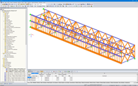
Indermühle Bauingenieure from the Swiss town of Thun was responsible for the timber engineering during the project phase including from the preliminary project to the supervision of the final design. The firm also completed the 3D project planning on behalf of the timber construction company. RFEM was utilized for the structural analysis.
Structure
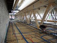
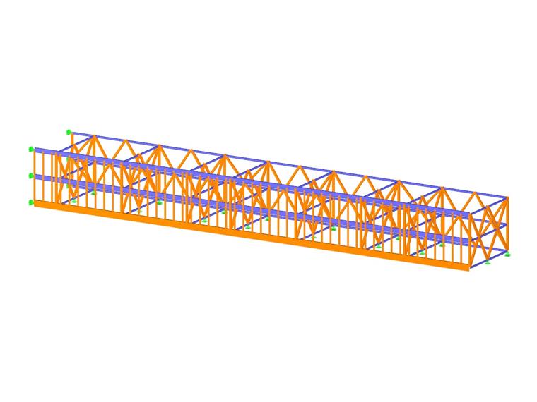
The additional floor consists of floor-to-ceiling trusses in the longitudinal and transverse directions. The truss diagonals are glued-laminated timber while the chords are steel. The chords are integrated in the timber-concrete composite floors.
The diagonals are connected with dowels and internal steel plates. The second floor cantilevers 10ft in the longitudinal direction and 13 ft in the transverse direction over the first floor.
The visible timber structure as well as the glazed exterior and interior walls create an intimate, open atmosphere.
Project Location
Contact us
Do you have questions or need advice?
Contact our free e-mail, chat, or forum support or find various suggested solutions and useful tips on our FAQ page.
Recommended Events
Timber Beam and Surface Structures | Part 1: Modeling, Load Input, Combinatorics
Webinar 05/04/2021 2:00 PM - 3:00 PM CEST
Eurocode 5 | Timber structures according to DIN EN 1995-1-1
Online Training 05/20/2021 8:30 AM - 12:30 PM CEST
Videos
Models to Download
Knowledge Base Articles

Digital Trends in Structural Analysis and Design
The construction industry is increasingly digitized. Structural engineers, a smaller group in the construction industry, are not always considered as engineers who immediately join the latest trends. Often for good reason.
Screenshots
Buildings made of cross-laminated timber (CLT), glued-laminated timber and OSB panels modeled with the RFEM program
Cantilevered new upper floor on the renovated ground floor of the school building in Sutz-Lattrigen (© Indermühle Bauingenieure)
Product Features Articles

The cross-section resistance design analyzes tension and compression along the grain, bending, bending and tension/compression as well as the strength in shear due to shear force.
The design of structural components at risk of buckling or lateral-torsional buckling is performed according to the Equivalent Member Method and considers the systematic axial compression, bending with and without compressive force as well as bending and tension. Deflection of inner spans and cantilevers is compared to the maximal allowable deflection.
Separate design cases allow for a flexible and stability analysis of members, sets of members, and loads.
Design-relevant parameters such as the stability analysis type, member slendernesses, and limit deflections can be freely adjusted.
Frequently Asked Questions (FAQ)
- For line releases, I obtain the resultants in the horizontal direction, which I cannot understand.
- When I apply an area load to a surface with an opening, the load is not not accounted for at the opening. Is it possible to automatically consider the area load as a line load around the opening perimeter?
- I just have to calculate an open hall with low roof loads and relatively high wind loads compared to it. In theory, a design of the bottom flange for buckling/toppling would have to be performed. Unfortunately, there is no combination of 1.0 * G +1.5 * W.
- How do I get the largest column load in my RFEM 3D model?
- In RF-/TIMBER AWC and RF-/TIMBER CSA, I receive the error that says torsion limit exceeded. How do I bypass this error message?
- Can I consider a reduction of the stiffness according to the German regulation NCI NA.5.9 in TIMBER Pro?
- Why is the strength always reduced by the kmod value of 0.6 during the calculation in the RF‑LAMINATE add‑on module, although I have load combinations with variable loads?
- I have selected all available members for design in RF-/TIMBER Pro. Why are tapered members not designed?
- When performing the fire resistance design with TIMBER Pro, I get the error 10001. How can I fix the error?
- Is it possible to set user-defined values when viewing solid stress results?
Customer Projects
Programs Used for Structural Analysis