Do you have any questions about Dlubal products or need assistance in selecting the right one for your project?
I'm here to help. You can easily reach me through the contact options provided below.
Looking forward to hearing from you!


Features of "Steel Joints" Add-on
_(1).png?mw=1024&hash=d0ff79e0e11dd59db70821050fffb969523e3261)
Features in Short
- Automatic generation of FE analysis models: The add-on automatically creates a finite element model (FE) of the steel connection in the background.
- Consideration of all internal forces: The calculation and design checks include all internal forces (N, Vy, Vz, My, Mz, MT) and are not limited to planar loading.
- Automatic load transfer: All load combinations are automatically transferred to the FE analysis model of the connection. The loads are transferred directly from RFEM, so manual data input is not necessary.
- Efficient modeling: The add-on saves you time when modeling complex connection situations. You can also save the created FE analysis model and use it further for your own detailed analyses.
- Extensible library: An extensive and extensible library with predefined steel connection templates is available.
- Wide applicability: The add-on is suitable for connections of any type and shape, compatible with almost all rolled, welded, built-up, and thin-walled cross-sections.

Basic Components of Steel Joints Add-on
- Numerous predefined components for easy input of typical connection situations (for example, end plates, angles, web plates)
- Universally applicable basic components (plates, welds, bolts, auxiliary planes) for the input of complex connection situations
- Graphical display of the connection geometry that is updated in parallel with the input
- The steel connection template included in the add-on allows you to select different connection types and apply them to your model
- The template provides connections from three categories: Rigid, Pinned, Truss
- Automatic adjustment of the connection geometry, even during subsequent editing of the structural components, due to the relative arrangement of the components to each other

New: Component "Base Plate" for Foundation Block Connections
The "Base Plate" component allows you to design base plate connections with cast-in anchors. In this case, plates, welds, anchorages, and steel-concrete interaction are analyzed.
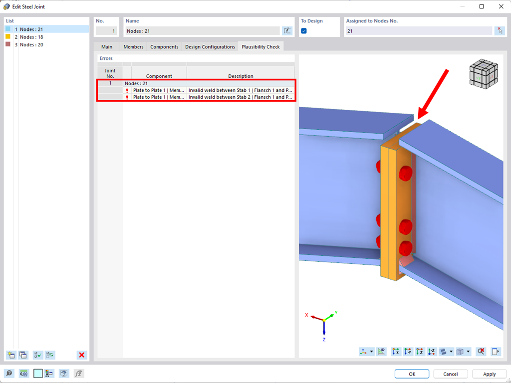

Plausibility and Collision Check for Connections
- Parallel to the input, a plausibility check is carried out by the program to quickly detect missing input or collisions.
- Bei einem Fehler erscheint eine Fehlermeldung, die das Problem beschreibt.
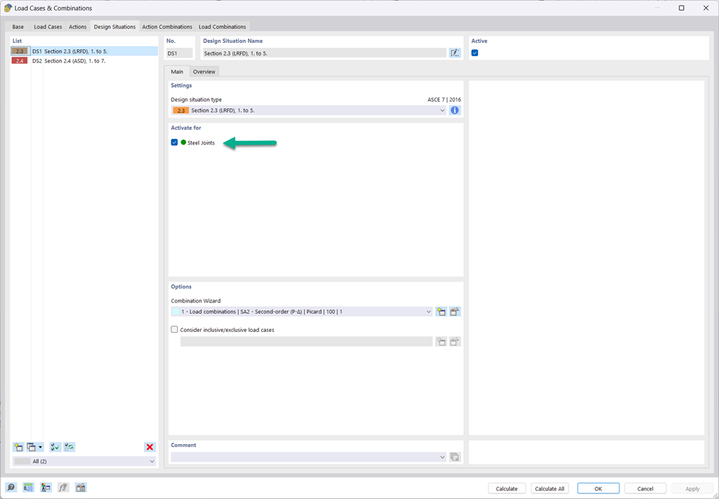
Design Situations for Steel Joints
- The design of the connection components is carried out according to AISC 360-16 and Eurocode EN 1993-1-8.
- After activating the add-on, the design situations for steel joints must be activated in the "Load cases and Combinations" dialog box.
- The "Structure Stability" add-on is required for the connection stability design (buckling).
- The calculation can be started via the table or the icon in the top bar.


Design According to AISC 360 and EN 1993-1-8
The program supports you: It determines the bolt forces on the basis of the FE analysis model and evaluates them automatically. The add-on performs the standard-compliant design of bolt resistance for failure cases, such as tension, shear, hole bearing, and punching, and clearly displays all required coefficients.
Do you want to perform weld design? The welds are modeled as elastic-plastic surface elements, and their stresses are read out from the FE analysis model. The plasticity criteria is set in the way that they represent failure according to AISC J2-4, J2-5 (strength of welds), and J2-2 (strength of base metal). The design can be performed with the partial safety factors of the selected National Annex of EN 1993‑1‑8.
The plates in the connection are designed plastically by comparing the existing plastic strain to the allowable plastic strain. The default setting is 5% according to EN 1993‑1‑5, Annex C, but can be adjusted by user-defined specifications, as well as 5% for AISC 360.
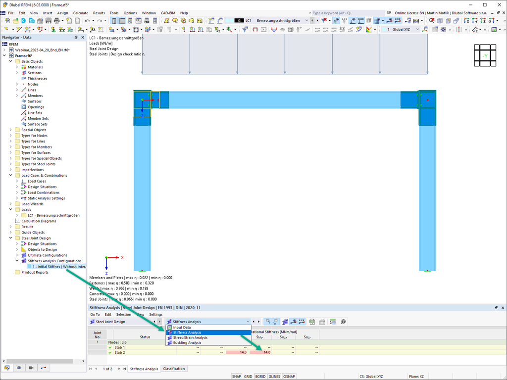
Anfangssteifigkeiten Sj,ini berechnen und automatisch in die Gesamtstruktur übertragen
The initial stiffness Sj,ini is a decisive parameter for evaluating whether a connection can be characterized as rigid, non-rigid, or hinged.
In the “Steel Joints” add-on, you can calculate the initial stiffnesses Sj,ini according to Eurocode (EN 1993-1-8 Section 5.2.2) and AISC (AISC 360-16 Cl. E3.4) in relation to the internal forces N, My, and/or Mz.
The optional automatic transfer of initial stiffnesses allows for a direct transfer as member end hinge stiffnesses in RFEM. Then, the entire structure is recalculated and the resulting internal forces are automatically adopted as loads in the calculation and design of the connection models.
This automated iteration process eliminates the need for manual export and import of data, reducing the amount of work and minimizing potential sources of error.
Explanatory Video: Calculation of Initial Stiffness Sj,ini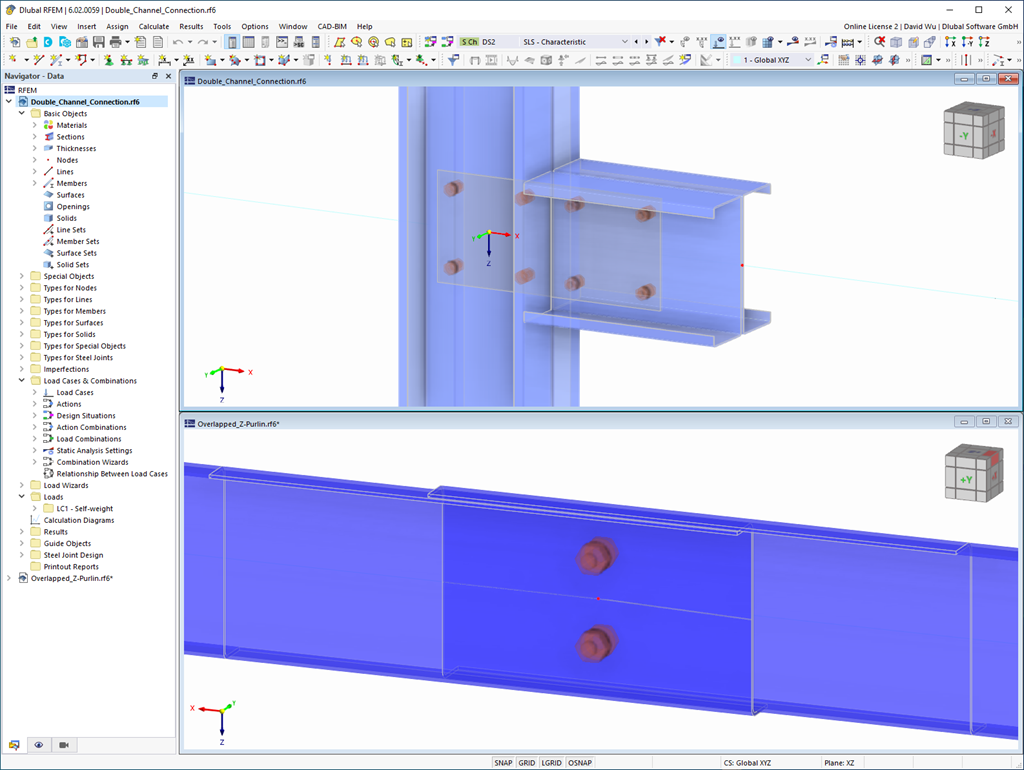
Steel Joint Design for Built-up and Thin-Walled Sections
In the Steel Joint add-on, you can design the connections of members with composite cross-sections. Furthermore, you can perform joint design checks for almost all thin-walled cross-sections in the RFEM library.
Go to Explanatory Video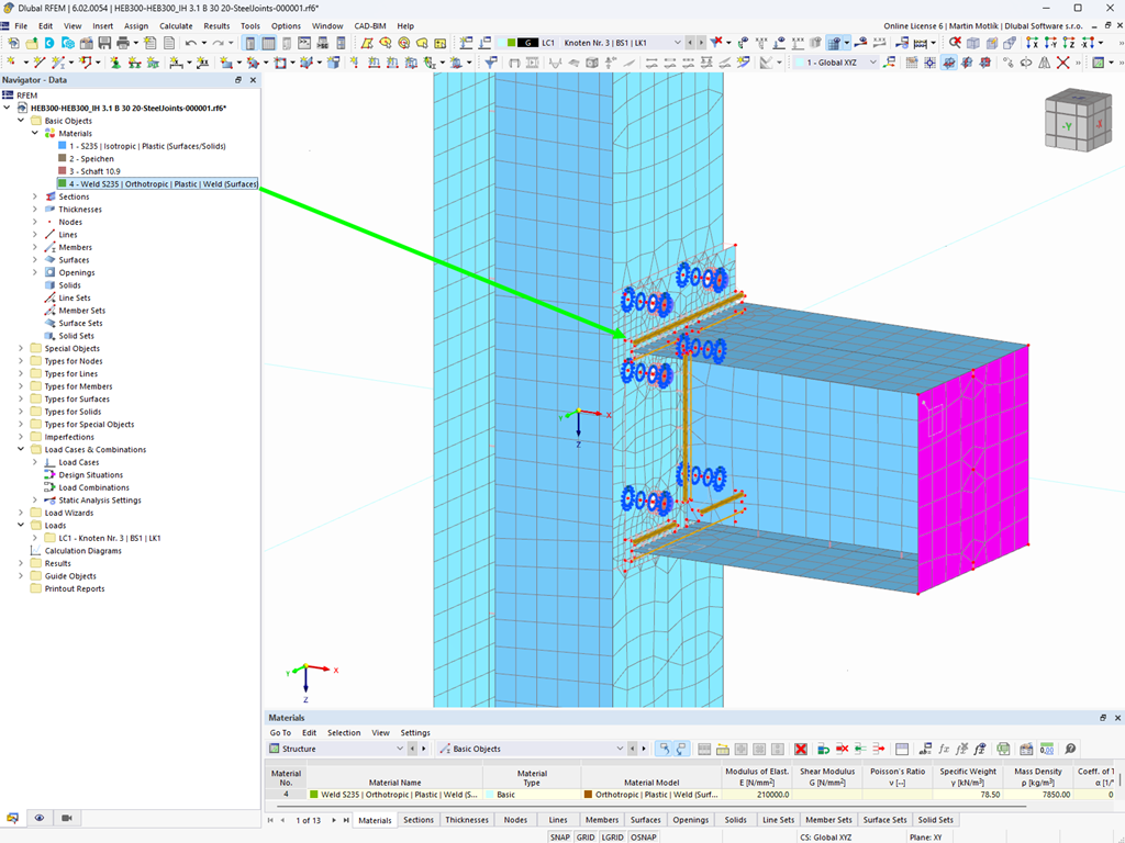
Plastic Material Model for Weld Design
Here, the weld design becomes child's play. Using the specially developed material model "Orthotropic | Plastic | Weld (Surfaces)", you can calculate all stress components plastically. The stress τperpendicular is also considered plastically.
Using this material model you can design welds closer to reality and more efficiently.
Explanatory Video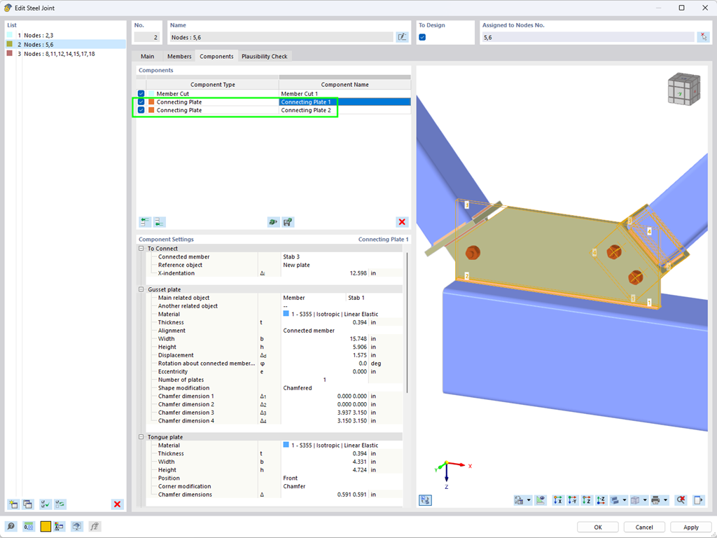
Component "Connecting Plate"
Using the "Connecting Plate" component, you can additionally and automatically create a new gusset plate in the Steel Joints add-on. This saves you separate components, and the other elements, such as a cap plate and a slide plate, are thus automatically taken into account with their dimensions.
Go to Explanatory Video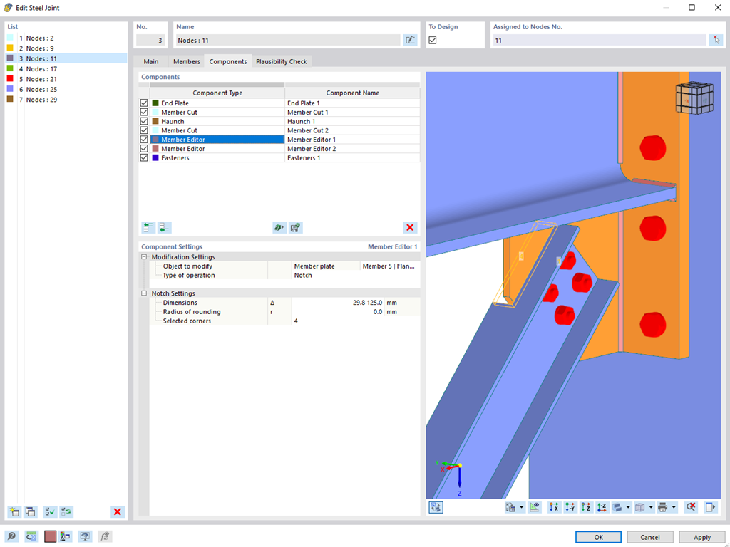
Component "Member Editor"
The "Member Editor" component allows you to modify the individual or several member plates in the Steel Joints add-on.
You can use the chamfer, notch, rounding, and hole operations with multiple shapes. It is possible to apply both operations, "Notch" and "Chamfer", for several member plates.
In this way, you can notch flanges from I-sections, for example (see the image).
Go to Explanatory Video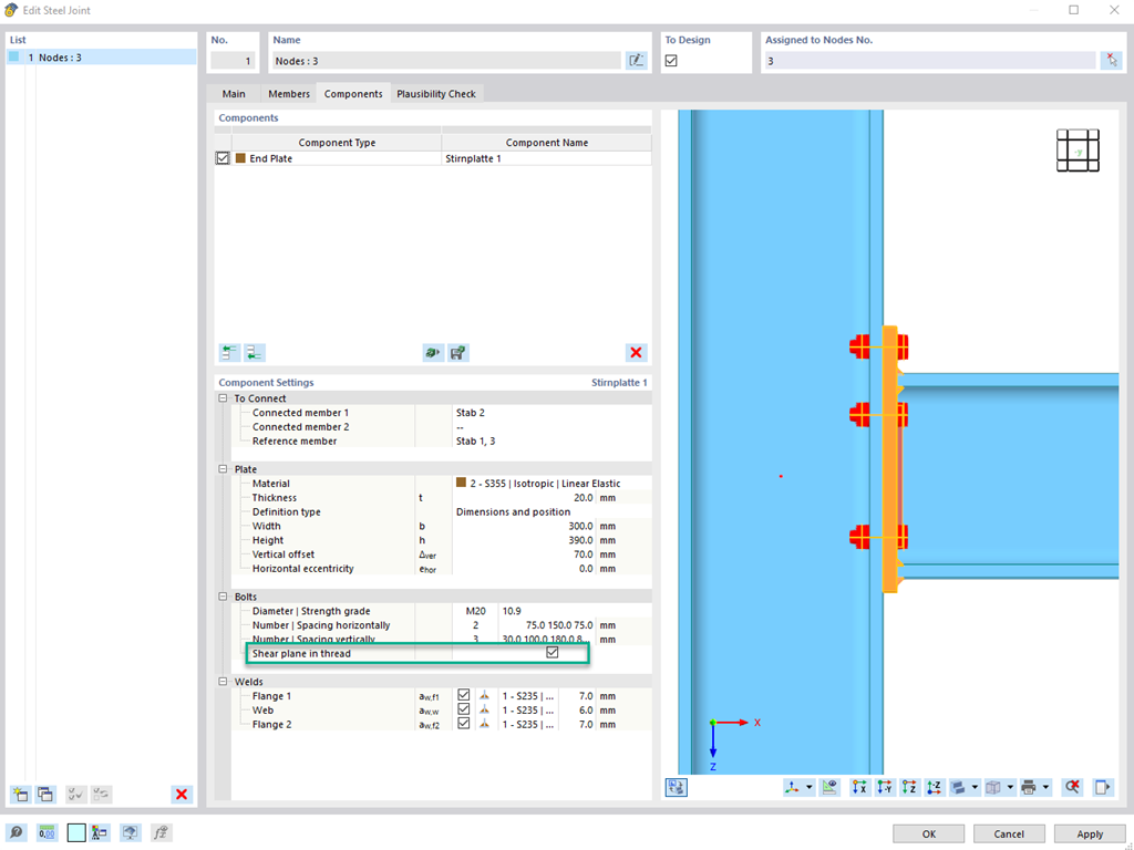
Shear Resistance of Bolts
To determine the shear resistance of bolts, you can use the Steel Joints add-on to specify whether there is a shaft or a thread in the shear plane.
Go to Explanatory Video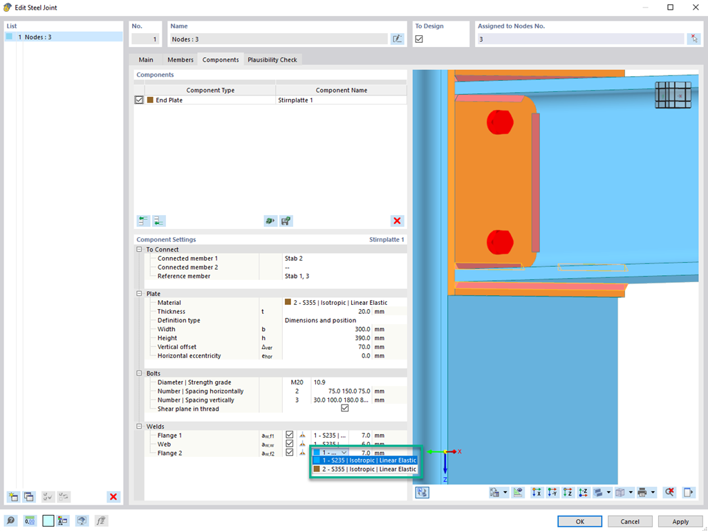
Material of Weld
If a weld seam connects two plates with different materials, it is possible to select from a combo box in the Steel Joints add-on which one of both materials should be used for the weld seam.
Go to Explanatory Video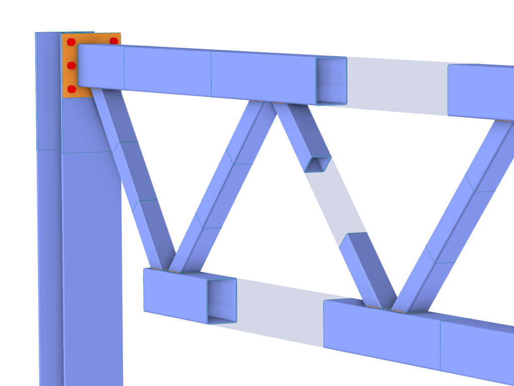
Connection of Rectangular Hollow Sections
In the case of rectangular cross-sections, you can usually achieve a direct connection by using welds. However, you can also connect them to other cross-sections in the same way. Furthermore, other components such as end plates help you to connect the rectangular cross-sections to other structural components.

Limit Plastic Strain for Welds
In the ultimate configuration of the steel joint design, you have the option to modify the limit plastic strain for welds.
.png?mw=192&hash=f63e4a3f1836233005de32f60201d5392e507cf1)
Calculate Your Price
The price is valid for United States. Prices are only valid for the software usage in United States. You can get exact prices after signing in. Please log on to your account at Dlubal Software to generate an updated quote.