Question:
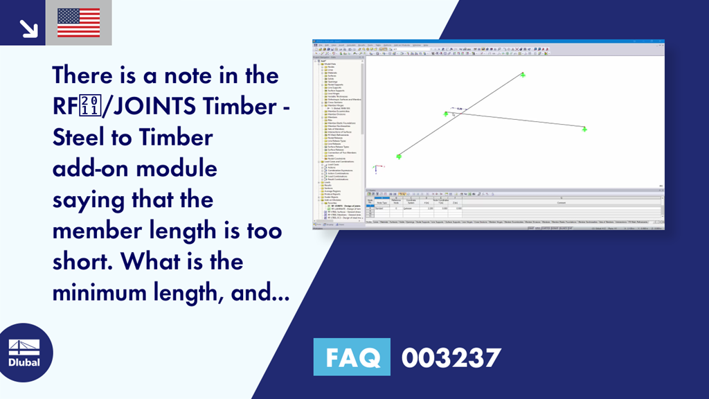
There is a note in the RF-/JOINTS Timber - Steel to Timber add-on module saying that the member length is too short. What is the minimum length, and how can I avoid the problem?
Answer:
To define a dowel connection, the add-on module requires the minimum member length. This is 42 cm. If a member is shorter, the text "Member is too short" appears in Window "1.2 Nodes and Members" (see Image 01). However, the structural component is often broken by intermediate nodes, and consists of several members. In such cases, the structural component can remain as a member in RFEM and the nodes can be used with the "Create Node 'On Line'" feature (see Image 02). Thus, the member is not divided. All members connected to these nodes are then connected to each other, even if the member is not divided. As an alternative, it is possible to use the "Divide Member" feature with the "Place new nodes on the line without dividing it" option (see Image 03).


.png?mw=350&hash=b2324c4db119938012b5490afaa56e9aa826cdcc)


.png?mw=600&hash=650b1058bf10a1f4e85c2911b3cca332da1e4b9f)
