


Shear Area Ay and Az
The shear area is determined from the cross-sectional area using the shear correction factor κ. It is calculated according to the corresponding theory, depending on the selection of a thin-walled or massive cross-section. The calculation for massive cross-sections is performed according to the GRASSHOF-ZURAVSKI theory (see also the program description for SHAPE-MASSIVE); for thin-walled cross-sections, the calculation of shear areas is described in this technical article.
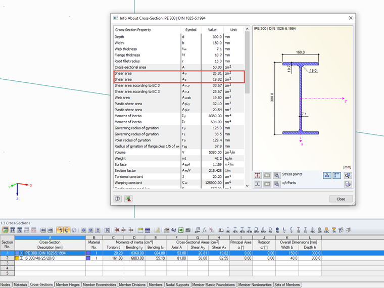
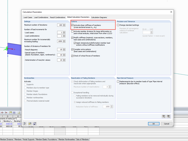
The shear area of cross-sections is used by default to determine the internal forces and moments as well as deformations in RSTAB/RFEM. However, the influence of the shear deformation can also be neglected by using the corresponding setting in the calculation parameters; then the cross-sections' shear areas will be irrelevant. Shear deformation effects on deformations and internal forces are described in this technical article showing an example in timber construction.
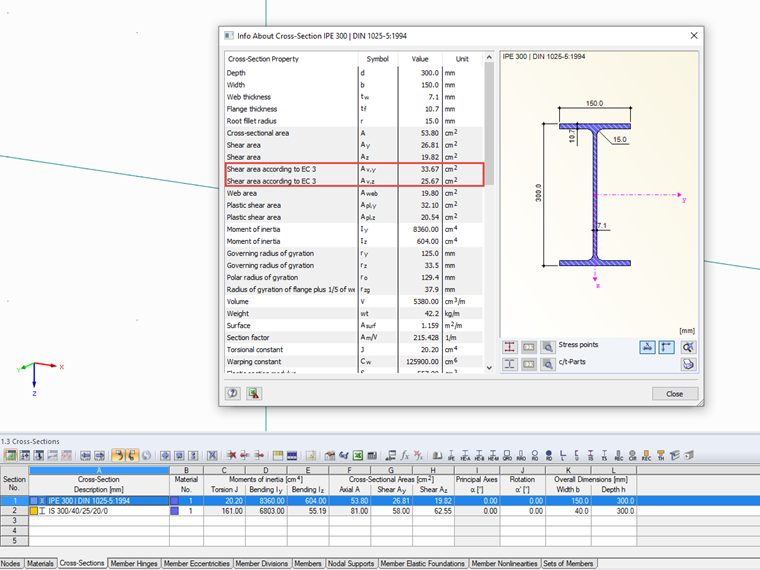
Effective Shear Area According to EC3 Av,z and Av,y
For the design, separate shear areas are usually determined according to the corresponding standards, such as the effective shear area according to EC 3. The calculation is described in Section 6.2.6 (Shear) depending on the cross-section shape.
This shear area is used in the RF-/STEEL EC3 add-on module to verify the design plastic shear resistance. However, if an elastic stress analysis is performed in RF-/STEEL, the shear area is not required because the determination of shear stresses is carried out independently by means of stress points.
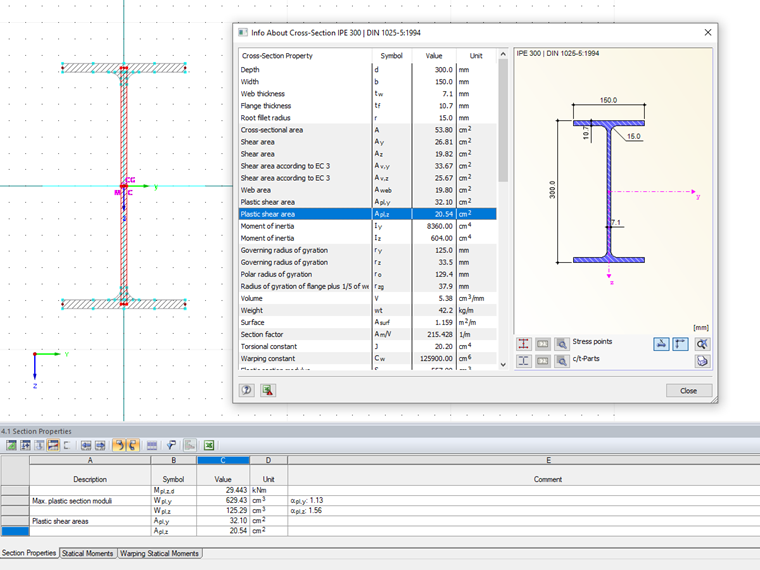
Plastic Shear Area Apl,z und Apl,y
The plastic shear area represents a simplified approach for determining the plastic shear resistance. First, the cross-section is decomposed into rectangular elements. The plastic shear area results from the area of the elements running parallel to the force direction; existing fillets as well as elements perpendicular to the considered force direction are not considered. Inclined elements will be considered with regard to the angle.
The SHAPE-THIN stand-alone program performs the calculation of the plastic shear areas according to the same method.
Differentiation of Thin-Walled and Massive Cross-Sections
For some cross‑sections, it is difficult to say whether it is a thin‑walled or a massive section. If the case is not clear-cut, it might be helpful to look at the shear areas Az or Ay.
As an example, the parametric I-section IS 300/40/25/20/0 is entered as a thin-walled cross-section. According to the thin-walled theory, a shear area Ay = 95.4 cm² is determined. Thus, it is larger than the cross-sectional area A = 81 cm², which may be an indication that the cross-section should actually be calculated as a massive cross-section. Therefore, before running the calculation in RSTAB/RFEM for a member having such a cross-section, a corresponding warning message appears due to the plausibility check.
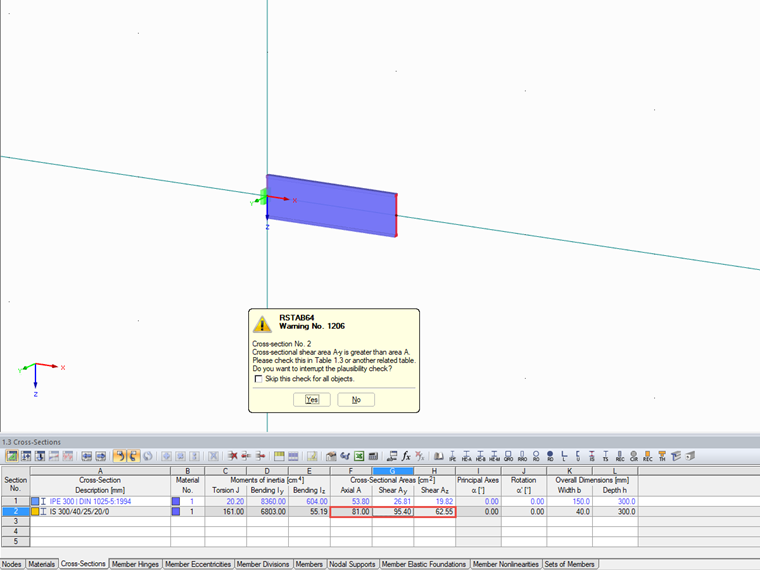
If the shear stiffness has been deactivated in the design parameters, this warning can be ignored without consequences. If you want to consider the shear stiffness, you can either use a parametric massive I-section or adjust the shear area manually in the table of cross-sections. Since the subsequent design performed in RF-/STEEL EC3 requires the definition as a thin-walled cross-section and the shear area is not used there anyway, we recommend adjusting the shear area of the cross-section defined as thin-walled.
