


Symbols Used
| h | Cross-section depth |
| L | Span |
| E | Modulus of elasticity |
| G | Shear modulus |
| κ | Shear correction factor |
| A | Cross-sectional area |
| w | Deformation |
This is due to the low shear modulus and low G/E ratio. This is given as 1/16 for softwood due to the anisotropy according to [1]. Isotropic materials provide a much larger ratio. For steel, for example, the result is a G/E ratio of 1/2.6.
Beam Theory
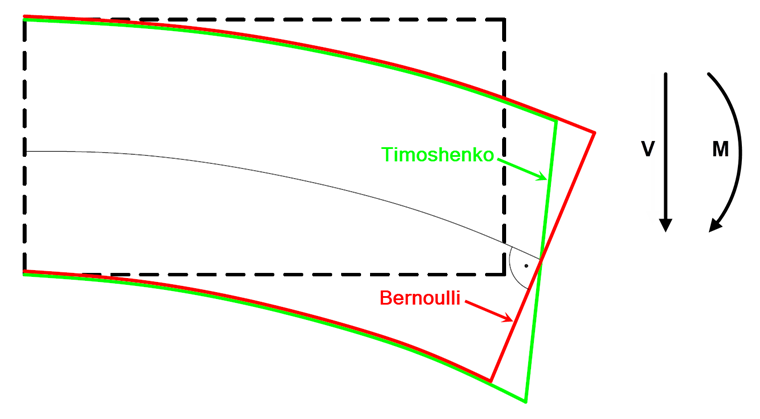
While the classical Bernoulli beam theory assumes that the cross-section of a member remains perpendicular to the member axis during its deformation, the Timoshenko beam theory (shear deformable beam) takes shear sliding into account. As a result, the cross-section of a member no longer remains perpendicular to the member axis when deformed (see Image 01). The assumption that the cross-section remains planar results in a uniform shear stress distribution along the beam height. However, as the distribution is parabolic, a shear correction factor is taken into account to determine the shear areas. This is 5/6 for a rectangular cross-section. Thus, the shear stiffness of a rectangular member results in:
Standards
The standard gives no indication as to whether the shear deformations for members have to be considered, or from which criterion. Therefore, the structural engineer has to make the decision.
Example
A simple example will demonstrate the influence of shear deformations. We consider a pinned single-span beam designed as a downstand beam. The details are shown in Image 02.
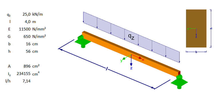
First, we only want to determine the deformation from the moment's curvature. For the system shown, the characteristic deformation is:
The component of the shear deformation can be derived, for example, with the working set or simplified from the investigations from [2] or [3]. For a pinned single-span beam, this results in:
The total deformation is thus:
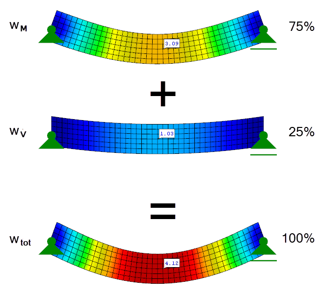
In this example, the shear deformation ratio is already 25% of the total deformation. Image 03 graphically shows the individual deformation components.
Slenderness
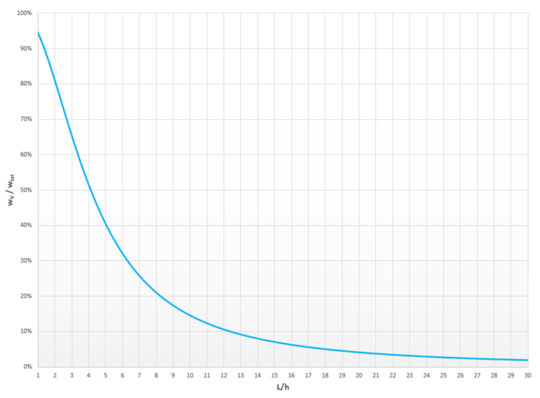
The slenderness of a member is decisive for the shear deformation component. While shear deformations are negligible for slender members with a large L/h ratio, they have a significant influence on compact members with a small L/h ratio.
Image 04 shows the influence of the shear deformation on the total deformation in a diagram. For hinged single-span beams with a rectangular cross-section, the shear deformation is predominant up to an L/h ratio of 4. Only then does the ratio predominate from the moment curvature. From an L/h ratio of 12, the influence of the shear deformation is only 10% of the total deformation.
Statically Indeterminate Systems
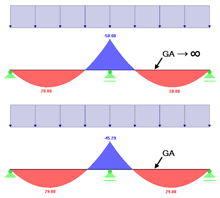
In statically indeterminate systems, shear deformation has a greater influence than in statically determined systems. In this case, the deformations due to shear force have an influence on the bending moment and thus also on the bending deformations. This redistribution may, for example, have a positive effect on supporting moments (see Image 05).
Shear Deformations in RFEM and RSTAB
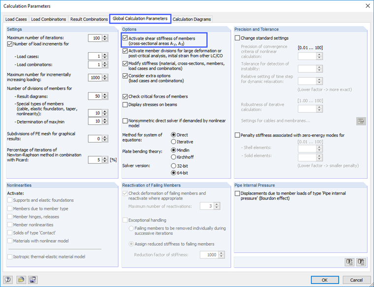
The shear deformations for members are automatically taken into account in RFEM and RSTAB. For control calculations, however, they can also be neglected with the function shown in Image 06. If the check box is selected, the shear deformations are considered. If it is deactivated, only the deformation components from the bending moment are considered.
Conclusion
In many practical situations, shear deformations can be neglected because they do not contribute significantly to the total deformation. For compact members, the shear deformation must not be neglected any longer. For RFEM and RSTAB, the shear deformation is always considered by default; for manual calculations, it is necessary to use tools (see [2] or [3]).
