


Another option for modeling with a member model was shown in this article.
In principle, this method can also be used for surfaces. Since the modeling of, for example, coupling members is time-consuming, we recommend coupling the surface directly to the member or the other surface. There are several options:
- Coupling Surface-Surface with Line Hinge
- Coupling Member-Surface with Line Release
- Coupling Surface-Surface with Contact Solid
The example from [1], Chapter E 8.6.2 shall serve as a reference. The structural system and the cross-section dimensions are shown in Figure 01. The flexibility is considered with 133 N/mm², which results from a fastener spacing of 125 mm.
![Structural System and Cross-Section Dimensions According to [1]](/en/webimage/009153/2417271/01-en-png.png?mw=760&hash=7ec548270c812e4679005b311ca774da4860d51a)
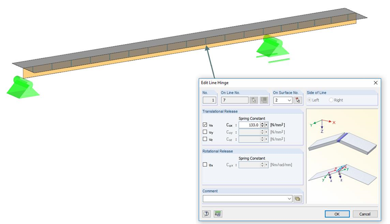
Coupling Surface-Surface with Line Hinge
The timber beam, as well as the concrete, will be modeled with surfaces here, whereas the surface of the timber beam will be created perpendicular to the surface of the concrete. Since the transversal strain is considered for surface elements, an orthotropic material model has to be selected for timber beams. At the composite joint, the flexibility can then be implemented with a line hinge by defining the flexibility for the degree of freedom ux in the shape of a spring. For the example from [1], it amounts to 133 N/mm².
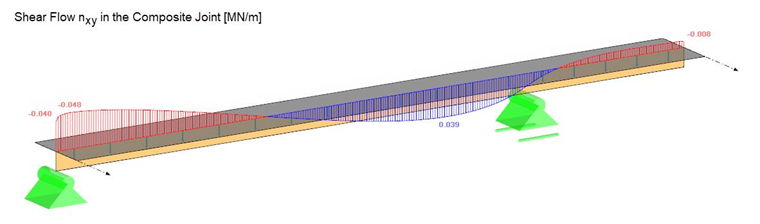
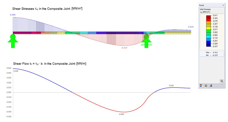
The advantage of this method is that the shear flow in the composite joint can be read off directly. It is possible to create a cut in the vertical surface and evaluate the basic internal force nxy. The results are identical to the shear analogy method from [1]. The decrease of the shear flow in the support area to 0.040 MN/m results from the singularity in this area and can be ignored.
One disadvantage might be that the stresses and superpositions have to be evaluated using the surface internal forces. However, it is possible that a result member integrates the surface results of the timber surface here, and a member design is thus ensured. To display the same centroidal distance of the single cross-sections, it would be necessary to arrange the concrete surface eccentrically by 35 mm. The influence in this case is very low; therefore, it is not considered here.
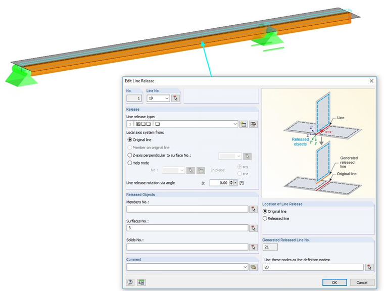
Coupling Member-Surface with Line Release
When using this method, the timber beam is modeled as a member and connected eccentrically to the surface. Since the surface is normally not connected to the member, but continues (effect of continuity), no line hinge can be used here. In this case, it is necessary to use the line release. Thus, it is possible to release one of the components and to control the relation to each other by a line release type. In this case, the flexibility can be considered in the same way as for the line hinge by a line spring.
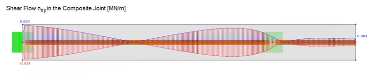
The disadvantage of this method is that it is no longer possible to read off the shear flow directly. In this case, a cut at the connection line of the surface to the member has to be created. This results in a shear flow to the left and right of this line. The result has to be added in this case. After the addition, the shear flow is identical to the previous method.
Update: In the meantime, a result output for line hinges and line releases has been created by which the shear flow can be read out directly. You can find the output in the Results navigator under "Releases".
However, the advantage here is that the design is, for example, possible in the RF-TIMBER add-on module since the internal forces are proportionately available.
Coupling Surface-Surface with Contact Solid
Another option is to couple both surfaces with a contact solid. Both surfaces are modeled parallel to each other and a contact condition in the shape of a contact solid is established in between. The timber beam also has to be modeled as an orthotropic surface. The flexibility is implemented in this case by a surface spring. It is necessary here to extend the line spring 133 N/mm² by one plane by dividing the value by the width of the contact surface; thus, 120 mm. The spring amounts to:
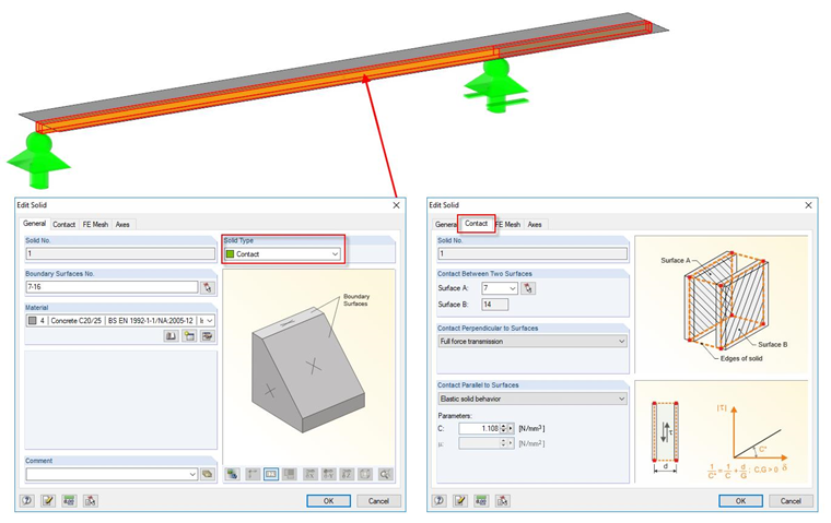
In this case again, the shear flow cannot be read off directly and has to be calculated from the shear stresses of the contact solid by multiplying the stresses again with 120 mm = 0.12 m. The result section can be exported to Excel and evaluated further there.
Since the surfaces are arranged geometrically, no eccentricity has to be defined. This modeling is certainly the most complex and only makes sense if the composite components are surface elements (for example, in the case of cross-laminated timber-concrete composite structures).