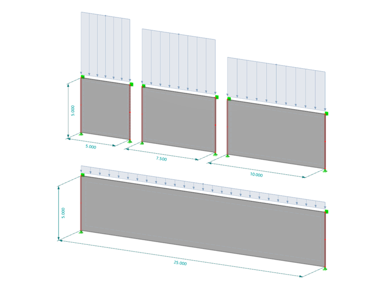
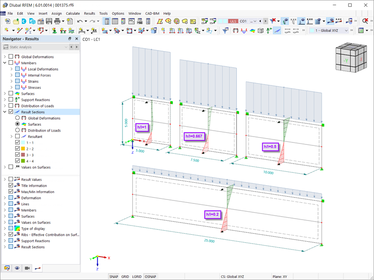
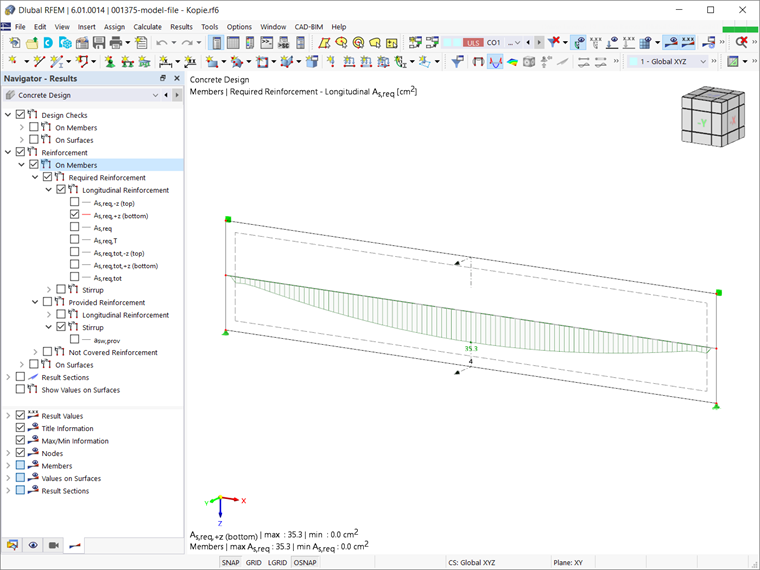
In RFEM 6, deep beams can be modeled as a surface of which the internal forces are calculated by considering elastic material behavior. The bending is transferred by the nonlinear distribution of the axial force, which varies depending on the ratio of height (h) to length (l). As shown in Image 1, the distribution approaches a straight line by lowering the h/l ratio. The design based on these internal forces results in a wedge-like distribution of the required longitudinal reinforcement (Image 2).
Given that the concrete design is based on a cracked state, the distribution of the required reinforcement has to be reconsidered. As a matter of fact, the strain of the reinforcement at the bottom edge may have been long exceeded, whereas the upper reinforcement layers have remained unaffected. To overcome this issue, there are two possible design approaches in RFEM 6: design using a result beam, or evaluation based on sections. The topic is also discussed in the Knowledge Base article:
Design Using Result Beam
This design approach is recommended for height-to-span ratios equal to or less than 0.5 (h/l ≤ 0.5); otherwise, the lever arm is assumed to be favorable.
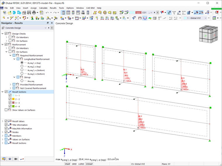
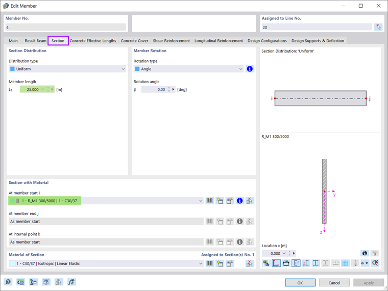
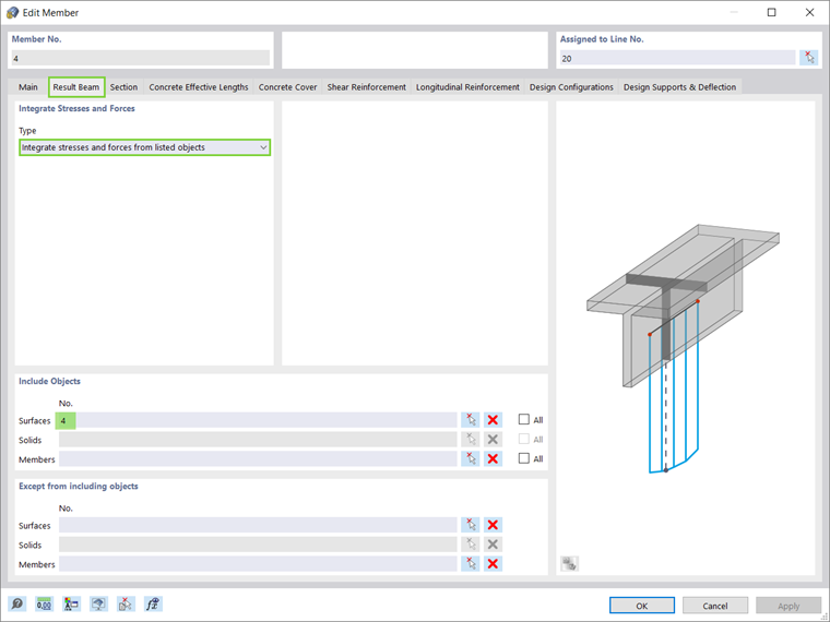
The result evaluation and design are done on a horizontal result beam created in the center of gravity. The cross‑section of this element is in line with the dimensions of the deep beam (Image 3). The stresses and forces are integrated from the deep beam, which has been modeled as a surface (Image 4). Hence, the design is performed on the result beam with the integrated internal forces of the deep beam. The results are then displayed as shown in Image 5.
Evaluation Based on Sections
When the ratio of height (h) to length (l) is greater than 0.5 (h/l > 0.5), evaluation based on sections is favorable. In this case, a vertical section is applied to the governing locations.
The evaluation of shear reinforcement is based on the maximum value of the vertical reinforcement (for example, from as,2,-z and as,2,+z), and is undiminished until the beam top edge has been created on both sides. For the bending reinforcement, on the other hand, it is necessary to sum up both horizontal reinforcements (for example, as,1,-z and as,1,+z).
The determined total longitudinal reinforcement is defined as concentrated at the bottom cross-section edge. For better evaluation of the reinforcement, we recommend displaying the results in terms of result sections, as shown in Image 5.

Reinforcement of Deep Beams
According to EN 1992-1-1:2004 (9.7), deep beams should be provided with an orthogonal reinforcement mesh near each face, with a minimum reinforcement area as given by the relevant National Annex.
The recommended minimum value is 0.1% of the cross-sectional area of the concrete, but no less than 150 mm²/m in each face and each direction. The distance between two adjacent bars of the mesh should not exceed twice the deep beam thickness or 300 mm, whichever is less.
Unless sufficient length is available between the node and the end of the beam permitting an anchorage length of "bd", the reinforcement corresponding to the ties considered in the design model should be fully anchored for equilibrium in the node (for example, by bending the bars, using U-hoops, or using anchorage devices).