


This window is displayed if at least one set of members is selected for design in window 1.1 General Data and the stability analysis is performed as per the general method according to [1] Section 6.3.4 (default setting).
If the Equivalent Member Method for sets of members is selected in the Details dialog box (see Figure 3.2), Window 1.7 is not displayed. In this case, lateral intermediate supports can be defined in Window 1.4 by using division points.
![]()

The current table manages the boundary conditions of the set of members that is selected on the left in the navigator!
The supports defined in RFEM or RSTAB (for example, in Z for a continuous beam) are not relevant in this window: The distributions of moments and shear forces for the determination of the amplification factor are automatically imported from RFEM/RSTAB. Here, you define the support conditions affecting the stability failure (buckling, lateral-torsional buckling). Supports on the start and end nodes of the set of members are preset. Any other supports, for example due to connected members, must be added manually. Use the
![]() button to select nodes graphically in the main program's work window.
button to select nodes graphically in the main program's work window.
According to [1] Section 6.3.4 (1), it is possible to design singly symmetric cross-sections that are stressed solely in their principal plane. For this analysis method, it is necessary to know the amplification factor αcr,op of the entire set of members. In order to determine this factor, the program creates a planar framework with four degrees of freedom for each node.
The orientation of the axes in the set of members is important for the nodal support definition. The program checks the position of the nodes and internally defines the axes of the nodal supports for Window 1.7 according to Figure 2.29 to Figure 2.32. The [Local Coordinate System] button below the model graphic can help you with the orientation: Use it to display the set of members in a partial view where the axes are clearly visible. You can find an example in the Knowledge Base on our website.
![]()
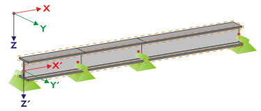
If all members of a set of members rest on a straight line, as shown in Figure 2.29, the local coordinate system of the first member in the set of members corresponds to the equivalent coordinate system of the entire set of members.
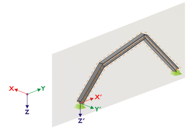
If the members of a set of members do not rest on a straight line, they still have to be located in the same plane. In Figure 2.30, the members rest in a vertical plane. In this case, the X'-axis is horizontal and oriented in the direction of the plane. The Y'-axis is horizontal as well and defined perpendicular to the X'-axis. The Z'-axis is oriented perpendicular downwards.
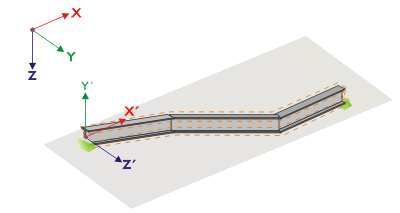
If the members of a buckled set of members rest in a horizontal plane, the X'-axis is defined parallel to the X-axis of the global coordinate system. Thus, the Y'-axis is oriented in the opposite direction to the global Z-axis, and the Z'-axis is directed parallel to the global Y-axis..

Figure 2.32 shows the general case of a buckled set of members: The members do not rest on a straight line, but in an inclined plane. The definition of the X'-axis results from the intersection line between the inclined and the horizontal plane. Thus, the Y'-axis is perpendicular to the X'-axis and in vertical position to the inclined plane. The Z'-axis is defined perpendicular to the X'-axis and Y'-axis.
The buttons below the graphic have the following functions:
|
|
Show members as a 3D rendering or a wire-frame model |
|
|
Show the current set of members or the entire model |
|
|
Show irrelevant members of a model as transparent or opaque |
|
|
Show a set of members with a local coordinate system or the entire model |
|
|
Show the view in the direction of the X-axis |
|
|
Show the view in the opposite direction of the Y-axis |
|
|
Show the view in the direction of the Z-axis |
|
|
Set an isometric view |
With the [Edit warp stiffener] button it is possible to determine the constant of a warp spring by the program.
![]()
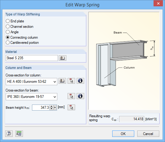
The following warp stiffening types are available in the Edit Warp Spring dialog box:
- End plate
- Channel section
- Angle
- Connecting column
- Cantilevered portion
Materials and cross-sections can be selected by using the lists and [Library] buttons.
![]()
The
![]() button allows you to also select them graphically in the RFEM/RSTAB model.
button allows you to also select them graphically in the RFEM/RSTAB model.
Based on the parameters, RF-/STEEL EC3 determines the Resulting warp spring Cω which can then be imported with [OK] in Window 1.7.
Warping Analysis with Seven Degrees of Freedom
To analyze sets of members according to the second-order analysis for flexural-torsional buckling with warping torsion, select the corresponding check box in the Warping Torsion tab of the Details dialog box (see Figure 3.9). The table titles of Window 1.7 will be adjusted accordingly.
![]()
The warping analysis requires a license of the RF-/STEEL Warping Torsion module extension.

Here, you define the support conditions of the set of members singled out from the system, which are available on the nodes of the members involved. Nodal supports defined in RFEM or RSTAB are preset, as well as supports on both ends of the set of members.
Lateral supports of the set of members must be added in the form of additional supports. In this way, you can model, for example, a purlin's effect given in the spatial model of RFEM or RSTAB. If this support is missing in the model of the singled out set of members, instabilities are possible.
Using the button, you can select the supported nodes graphically in the RFEM/RSTAB work window.
In Columns B to N, you can specify the support conditions of the selected nodes. To activate or deactivate the supports and restraints for the corresponding degrees of freedom, click in the check boxes. As an alternative, you can enter the constants of the translational and rotational springs manually.
The Support rotation and Eccentricity parameters allow for modeling support conditions close to reality.
You can find an example describing the warping torsion analysis of a tapered single-span beam in an article of our Knowledge Base on our website.
The warping analysis of a frame is also the topic of a webinar, which you can watch or download on Youtube.
Literature
[1] Eurocode 3: Design of steel structures - Part 1-1: General rules and rules for buildings; EN 1993-1-1:2010-12