


Strengths
The following table shows the strengths that are relevant for the stress analysis of cross-laminated timber.
| Symbol | Strength | Graphic |
|---|---|---|
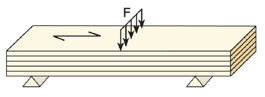
| fm,0,k | Flexural strength | |
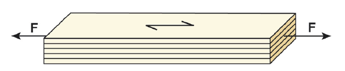
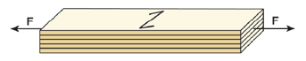
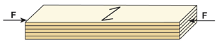
| ft,0,k | Tensile strength | |
| ft,90,k | Tensile strength perpendicular | |
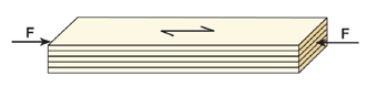
| fc,0,k | Compressive strength | |
| fc,90,k | Compressive strength perpendicular | |
| fv,xz,k | Shear strength | |
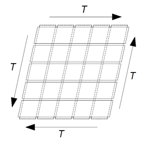
| fv,xy,k | Shear strength (Failure Mode 1) | |
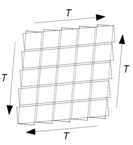
| fv,net,k | Shear strength (Failure Mode 2) | |
| fv,tor,k | Shear strength (Failure Mode 3) | |
| fv,yz,k | Rolling shear strength |

The basic stresses are calculated in RFEM using the finite element method. The corresponding equations are presented in the chapter Stresses of the RFEM manual.
Basic Equation
Strain Calculation
Bending Stresses
The strain is determined according to the above equation as follows:
In the case of pure bending stress without axial force, the calculation of the total strain is simplified by using the inverse of the total panel stiffness. This is displayed for the X-direction in the following equation.
The stress for a complete structure is determined from this total strain. The stress at the individual integration points is then calculated using the local stiffness matrix of each layer.
The following image shows this process using a three-layer panel as an example. The stress distribution on the left represents the initial stress, while the stress distribution on the right represents the resulting stress in each layer. Since the middle layer in this example has a modulus of elasticity Ey = 0, there can be no significant stress there.
Shear Stresses
Three types of failure modes (FM) can be distinguished for shear stress in the panel plane.
Failure Mode 1
Failure Mode 2

|
nxy |
Shear force |
|
ex, ey |
Plank width with gap in the x or y direction |
|
bx, by |
Brettbreite in x- oder y-Richtung |
Failure Mode 3
In principle, this failure mode corresponds to torsion design. It is verified here that the shear stresses caused by the shearing of the intersection surfaces of the overlapping boards do not become too great.
The value ex or ey refers to the board width in the x or y direction with the joint.
Rolling Shear Stresses
The rolling shear stresses are taken into account using the resultant of the shear stresses in the thickness direction x and y via the following equation.
With a typical orientation of a cross-laminated timber panel of 0° / 90° for the individual layers, the shear stress in the x and y direction is therefore compared with the rolling shear.