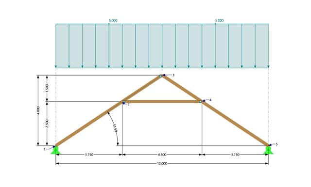
A collar beam roof with the selected geometry is compared in terms of its internal forces between the calculation using RFEM 6 and the manual calculation. In total, three load systems are analyzed.

This example compares the effective lengths and critical load factor, which can be calculated in RFEM 6 using the Structure Stability add-on, with a manual calculation. The structural system is a rigid frame with two additional hinged columns. This column is loaded by vertical concentrated loads.
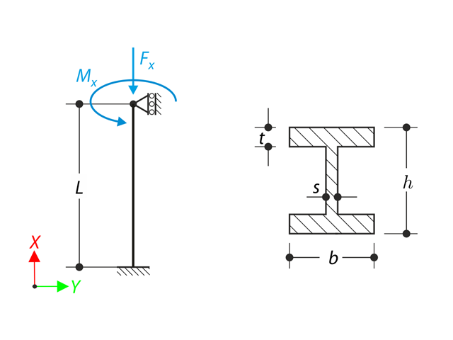
A member with the given boundary conditions is loaded by torsional moment and axial force. Neglecting its self-weight, determine the beam's maximum torsional deformation as well as its inner torsional moment, defined as the sum of a primary torsional moment and torsional moment caused by the normal force. Provide a comparison of those values while assuming or neglecting the influence of the normal force. The verification example is based on the example introduced by Gensichen and Lumpe.
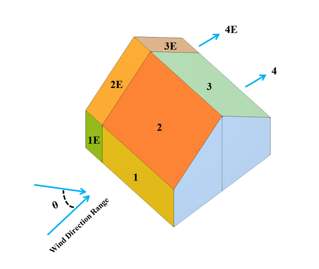
In the current validation example, we investigate wind pressure coefficient (Cp) for both main structural members (Cp,ave) and secondary structural members such as cladding or façade systems (Cp,local) based on NBC 2020 [1] and Japanese Wind Tunnel Data Base for low-rise building with 45 degree slope. The recommended setting for three-dimensional flat roof with sharp eaves will be described in the next part.
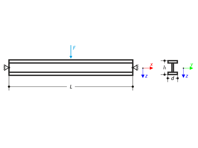
Beam pinned at the both ends is loaded by means the transversal force at the middle. Neglecting its self-weight and shear stiffness, determine the maximum deflection, normal force and moment at the mid-span assuming the second and the third order theory. The verification example is based on the example introduced by Gensichen and Lumpe (see the reference).
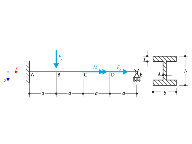
A beam is fully fixed (warping is restricted) on the left end and supported by a fork support (free warping) on the right end. The beam is subjected to a torque, longitudinal force, and transverse force. Determine the behavior of the primary torsional moment, secondary torsional moment and warping moment. The verification example is based on the example introduced by Gensichen and Lumpe (see reference).
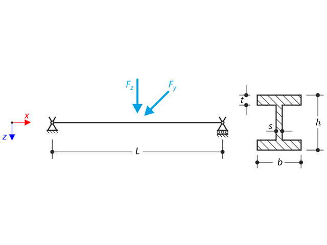
The axial rotation of the I-profile is restricted on the both ends by means of the fork supports (warping is not restricted). The structure is loaded by two transverse forces in its middle. The self-weight is neglected in this example. Determine the maximum deflections of the structure uy,max and uz,max, maximum rotation φx,max, maximum bending moments My,max and Mz,max and maximum torsional moments MT,max, MTpri,max, MTsec,max and Mω,max. The verification example is based on the example introduced by Gensichen and Lumpe.
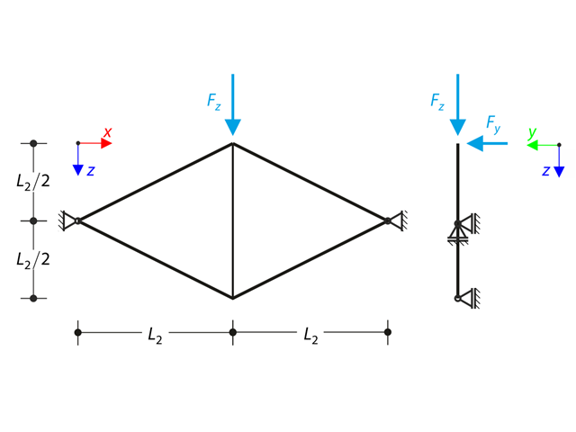
Planar truss consisting of four sloped members and one vertical member is loaded at the upper node by means of the vertical force Fz and out of plane force Fy. Assuming large deformation analysis and neglecting self-weight, determine the normal forces of the members and the out of plane displacement of the upper node uy. The verification example is based on the example introduced by Gensichen and Lumpe.
In the current validation example, we investigate wind pressure value for both general structural design (Cp,10) and local structural design such as cladding or façade systems (Cp,1) based on EN 1991-1-4 flat roof example [1] and Japanese Wind Tunnel Data Base . The recommended setting for three-dimensional flat roof with sharp eaves will be described in the next part.

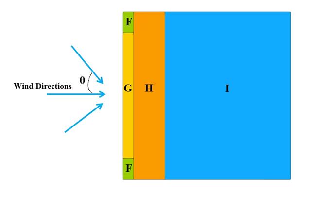
In the current validation example, we investigate wind pressure coefficient (Cp) of flat roof and walls with ASCE7-22 [1]. In the section 28.3 (Wind loads - main wind force resisting system) and Figure 28.3-1 (load case 1), there is a table which shows Cp value for different roof angle.