Description
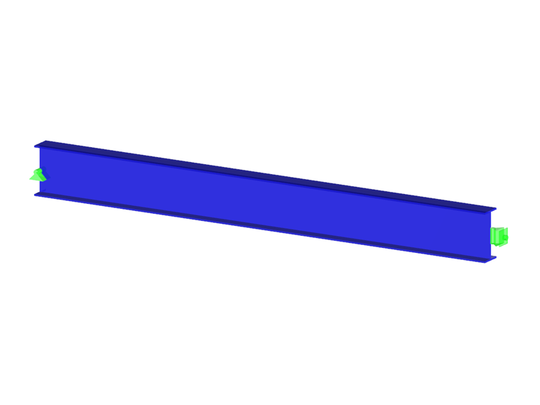
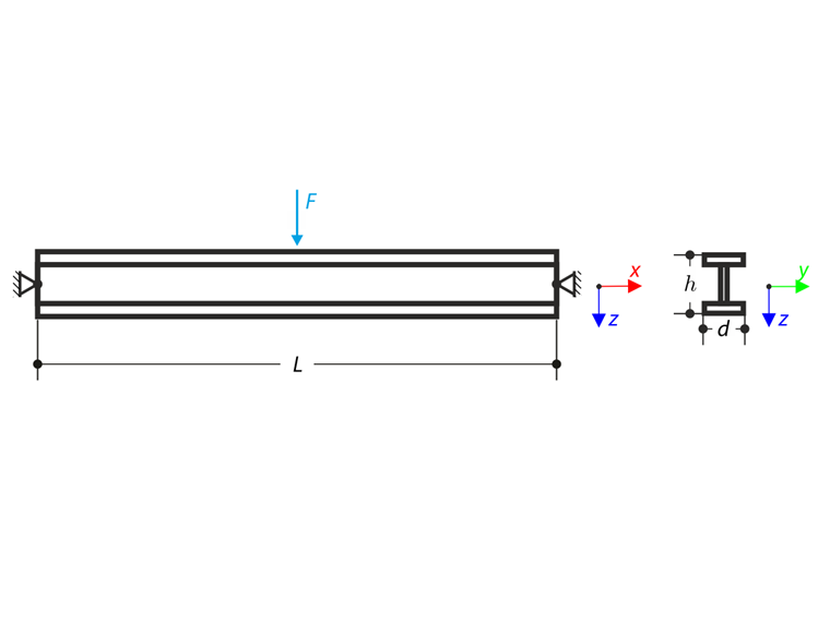
Beam pinned at the both ends is loaded by means the transversal force at the middle. Neglecting its self-weight and shear stiffness, determine the maximum deflection, normal force and moment at the mid-span assuming the second and the third order theory. The verification example is based on the example introduced by Gensichen and Lumpe (see the reference).
| Material | Steel | Modulus of Elasticity | E | 210000.000 | MPa |
| Shear Modulus | ν | 81000.000 | MPa | ||
| Yield Stress | fy | 355.000 | MPa | ||
| Geometry | Beam | Length | L | 8.000 | m |
| Height | h | 0.400 | m | ||
| Width | b | 0.180 | m | ||
| Web Thickness | s | 0.010 | m | ||
| Flange Thickness | t | 0.014 | m | ||
| Load | Transversal Force | F | 215.000 | kN | |
Analytical Solution
Analytical solution is not available. Results from software S3D are taken as reference.
RFEM and RSTAB Settings
- Modeled in version RFEM 5.32, RSTAB 8.32 and RFEM 6.02, RSTAB 9.02
- The element size is lFE = 0.800 m
- The element type is member
- Isotropic linear elastic material model is used
- Shear stiffness of members is deactivated
Results
| Second-Order Analysis | S3D | RFEM 6 | Ratio | RSTAB 9 | Ratio |
| uz1(L/2) [mm] | 47.3 | 47.3 | 1.000 | 47.3 | 1.000 |
| My(L/2) [kNm] | 430 | 430 | 1.000 | 430 | 1.000 |
| N(L/2) [kN] | 0 | 0 | - | 0 | - |
| Second-Order Analysis | S3D | RFEM 5 | Ratio | RSTAB 8 | Ratio |
| uz1(L/2) [mm] | 47.3 | 47.3 | 1.000 | 47.3 | 1.000 |
| My(L/2) [kNm] | 430 | 430 | 1.000 | 430 | 1.000 |
| N(L/2) [kN] | 0 | 0 | - | 0 | - |
| Large Deformation Analysis | S3D | RFEM 6 | Ratio | RSTAB 9 | Ratio |
| uz1(L/2) [mm] | 46.4 | 46.4 | 1.000 | 46.4 | 1.000 |
| My(L/2) [kNm] | 423 | 423 | 1.000 | 423 | 1.000 |
| N(L/2) [kN] | 147 | 147 | 1.000 | 147 | 1.000 |
| Large Deformation Analysis | S3D | RFEM 5 | Ratio | RSTAB 8 | Ratio |
| uz1(L/2) [mm] | 46.4 | 46.4 | 1.000 | 46.4 | 1.000 |
| My(L/2) [kNm] | 423 | 423 | 1.000 | 423 | 1.000 |
| N(L/2) [kN] | 147 | 147 | 1.000 | 147 | 1.000 |