19 Results
View Results:
Sort by:
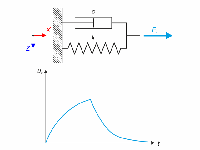
Kelvin-Voigt material model consists of the linear spring and viscous damper connected in parallel. In this verification example there is tested the time behaviour of this model during the loading and relaxation in a time interval 24 hours. The constant force Fx is applied for 12 hours and the rest 12 hours is the material model free of load (relaxation). The deformation after 12 and 20 hours is evaluated. Time History Analysis with Linear Implicit Newmark method is used.
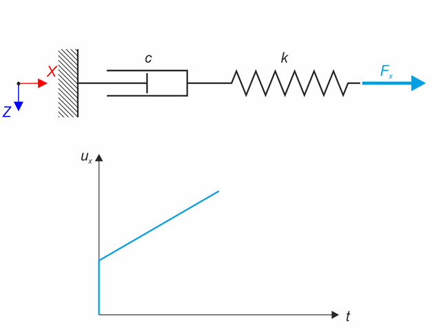
Maxwell material model consists of the linear spring and viscous damper connected in series. In this verification example there is tested the time behaviour of this model. The Maxwell material model is loaded by constant force Fx. This force causes initial deformation thanks to the spring, the deformation is then growing in time due to the damper. The deformation is observed at time of loading (20 s) and at the end of the analysis (120 s). Time History Analysis with Linear Implicit Newmark method is used.

In this example, the shear at the interface between concrete cast at different times and the corresponding reinforcement are determined according to DIN EN 1992-1-1. The obtained results with RFEM 6 will be compared to the hand calculation below.

A reinforced concrete beam is designed as a two-span beam with a cantilever. The cross-section varies along the length of the cantilever (tapered cross-section). The internal forces, the required longitudinal and shear reinforcement for the ultimate limit state are calculated.

In this verification example, the capacity design values of shear forces on beams are calculated in accordance with EN 1998-1, 5.4.2.2 and 5.5.2.1 as well as the capacity design values of columns in flexure in accordance with 5.2.3.3(2). The system consists of a two span reinforced concrete beam with a span length of 5.50m. The beam is part of a frame system. The results obtained are compared with those in [1].

An inner column in the first floor of a three-story building is designed. The column is monolithic connected with the top and bottom beams. The fire design simplified method A for columns according to EC2-1-2 is than proofed and the results compared to [1].
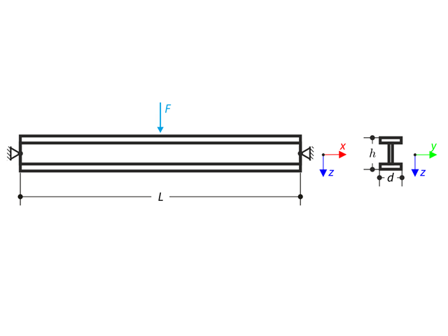
Beam pinned at the both ends is loaded by means the transversal force at the middle. Neglecting its self-weight and shear stiffness, determine the maximum deflection, normal force and moment at the mid-span assuming the second and the third order theory. The verification example is based on the example introduced by Gensichen and Lumpe (see the reference).

The model is based on the example 4 of [1]: Point-supported slab.
The flat slab of an office building with crack-sensitive lightweight walls is to be designed. Inner, border and corner panels are to be investigated. The columns and the flat slab are monolithically joined. The edge and corner columns are placed flush with the edge of the slab. The axes of the columns form a square grid. It is a rigid system (building stiffened with shear walls).
The office building has 5 floors with a floor height of 3.000 m. The environmental conditions to be assumed are defined as "closed interior spaces". There are predominantly static actions.
The focus of this example is to determine the slab moments and the required reinforcement above the columns under full load.
The model is based on the example 4 of [1]: Point-supported slab. The internal forces and the required longitudinal reinforcement can be found the in verification example 1022. In this example, punching is examined in the axis B/2.

An ASTM A992 W 24×62 beam with end shears of 48.000 and 145.000 kips from the dead and live loads, respectively, is shown in Figure 1. Verify the available shear strength of the selected beam, based on LRFD and ASD.
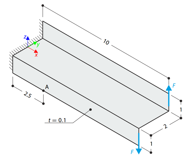
A Z-Section Cantilever is fully fixed at the end and loaded by a torque which, in the case of a shell model, is represented by a couple of shear forces. Determine the axial stress at point A (at mid-surface). The problem is defined according to The Standard NAFEMS Benchmarks.
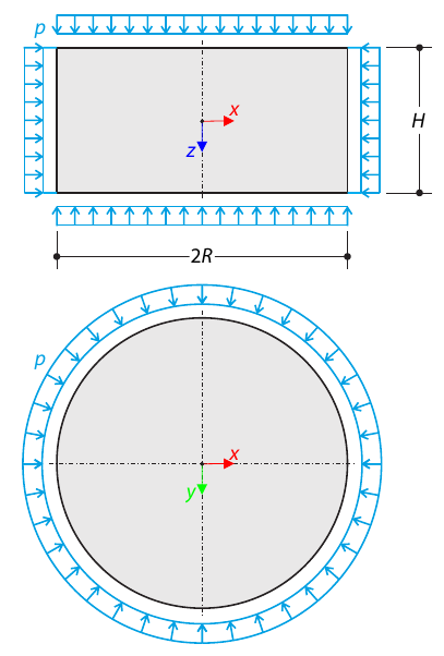
A cylinder made of elasto-plastic soil is subjected to triaxial test conditions. Neglecting the self-weight, the goal is to determine the limit vertical stress for shear stress failure. An initial hydrostatic stress of 100 kPa is considered.
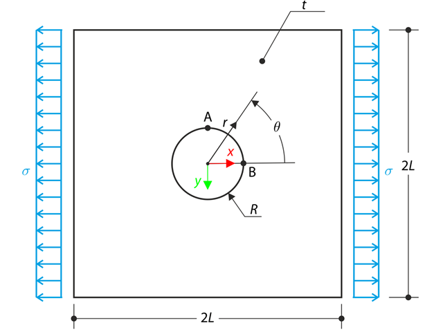
The wide plate with a hole is loaded in one direction by means of the tensile stress σ. The plate width is large with respect to the hole radius and it is very thin, considering the state of the plane stress. Determine the radial stress σr, tangential stress σθ, and shear stress τrθ around the hole.
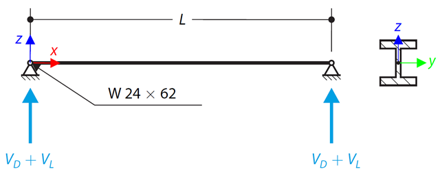
An ASTM A992 W 24×62 beam with end shears of 48.000 and 145.000 kips from the dead and live loads, respectively, is shown in Figure 1. Verify the available shear strength of the selected beam, based on LRFD and ASD.
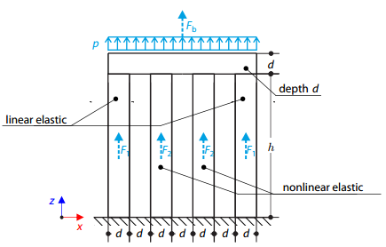
Four columns are fixed at the bottom and connected by a rigid block at the top. The block is loaded by pressure and modeled by an elastic material with a high modulus of elasticity. The outer columns are modeled by linear elastic material and the inner columns by a stress-strain diagram with decaying dependence. Assuming only the small deformation theory and neglecting the structure's self-weight, determine its maximum deflection.
A beam pinned at both ends is loaded with concentrated force in the middle. Neglecting its self-weight and shear stiffness, determine the beam's maximum deflection, normal force, and moment at the mid-span, assuming the second- and third-order analysis.
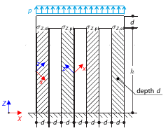
Determine the maximum deflection of four columns fixed at the bottom and connected by a rigid block at the top. The block is loaded by pressure and modeled by an elastic material with a high modulus of elasticity. The outer columns are modeled as orthotropic elastic material, and the inner columns as orthotropic elastic-plastic material with the same elastic parameters as the outer columns and plasticity properties defined according to the Tsai-Wu plasticity theory.
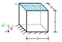
Determine the maximum deflection of a cube. The cube's lower side is fully fixed and the upper side is subjected to shear loading.
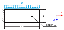
Determine the maximum deflections of the block while considering or neglecting shear effect. The square block of the isotropic material is fully fixed at one end and loaded with uniform vertical pressure.