


The bridge connects the cities of Solingen and Remscheid. Approximately 120 years of rail traffic and climatic conditions have led to various damage to the structure. In addition, the changed requirements of the currently valid regulations resulted in deficits in the component designs. This meant that the structure had to be completely renovated to ensure it could be used for at least another 30 years.
The structural recalculation of the bridge was carried out by IWS Ingenieure. The check of the bridge analysis was carried out by PSP - Professor Sedlacek and Partner using RSTAB.
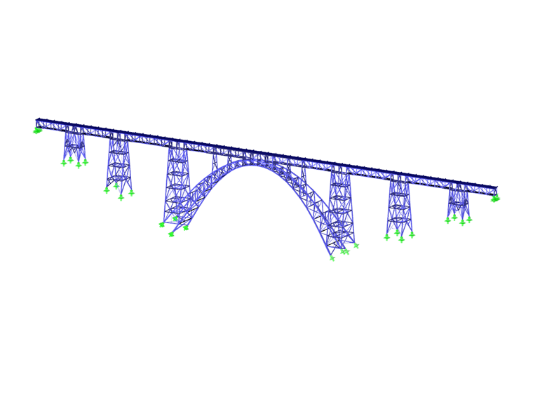
Structure
The bridge has a total length of 465 m (1,525 ft). It consists of an arc construction with a span of 170 m (577 ft) and trestle bridges on both sides with individual lengths of 30 m (98 ft) and 45 m (147 ft), which are supported on roller bearings on truss pillars.
On the upper side is the lane, designed as an open girder grillage, with a two‑rail track superstructure on top.
Recalculation
The calculation for the operation and for the check was performed on the 3D framework model. The modeling was carried out in consideration of the detected damage. For example, special attention was paid to the structure's hinge points to display roller bearings with limited movement close to reality.
In contrast to the original structural analysis, 13 structural load cases were considered for the first time as well. For example, position manipulation of the truss arc. At that time, it was set up in the classic cantilever construction method with a cantilever length of up to 30 m (98 ft). The construction stages have a significant influence on the stress condition for the load case self‑weight.
In addition to the usual linearly variable loads from temperature, wind, acceleration/braking and lateral impact, 3 traffic loads (load effect UIC71 and so on) were applied. The recalculation was verified and calibrated by, among other things, test runs conducted under load conditions.
Results and Rehabilitation
With the recalculation, it was possible to calculate the damage on the structure. In individual structural components such as longitudinal and secondary beams of the road, wind bracings, and anchorages, design ratios of over 200% were reached in some cases. This led to the decision that the bridge must be thoroughly reconstructed.
The most serious intervention was the replacement of the bridge lane, which required complete closure of the railroad line. Moreover, it was necessary to reduce the load level. The rehabilitation of the trestle bridges, pillars, foundation elements, and the arc can take place during reduced rail operation.
With the decision to rehabilitate the Müngsten Bridge despite the high financial investments, an outstanding steel bridge structure is preserved.
| Location | Müngstener Brückenweg 42659 Solingen, Germany |
| Client |
DB Netz AG, production in Düsseldorf, Germany www.dbinfrago.com |
| Project Management | DB Engineering & Consulting GmbH, Cologne, Germany db-engineering-consulting.com |
| General Planning | IGS Ingenieure GmbH & Co. KG www.igs-ib.de |
| Structural Reanalysis | IWS Beratende Bauingenieure www.iws-idstein.de |
| Check of Structural Analysis | PSP - Professor Sedlacek und Partner, Dortmund, Germany www.psp-ingenieure.de |


