Tennis Court Tension Membrane Roof in Belin-Béliet, France
Customer Project
-
01
RFEM Tennis Court Roof Model (© ACS Production)
-
01
Aerial View of Tennis Court in Belin-Béliet (© ACS Production)
-
01
Tensioned Membrane Tennis Court Roof (© ACS Production)
-
01
Tensioned Membrane Tennis Court Roof in Belin-Béliet, France
-
01
Stretched Canvas Roof of Tennis Court in Belin-Béliet, France
-
04
Tensioned Membrane Tennis Court Roof in Belin-Béliet, France
-
04
RFEM Tennis Court Roof Model (© ACS Production)
-
04
Aerial View of Tennis Court in Belin-Béliet (© ACS Production)
-
04
Tensioned Membrane Tennis Court Roof (© ACS Production)
-
04
Stretched Canvas Roof of Tennis Court in Belin-Béliet, France
The Belin-Béliet (department of Gironde) municipality tennis club, founded in 1976, completed a new tennis hall in July 2019. This project was made possible due to a subsidy provided by the French Tennis Federation along with the support of the municipality.
Investor |
Tennis club Belin-Béliet, France www.tennis-belinbeliet.fr |
Construction Management | Architectural office of Bruno Amblard, Saint-Magne, France |
Concept and Realization |
ACS Production, Montoir de Bretagne, France www.acs-production.com |
Model
ACS Production provided the tensioned canvas roof structural analysis and design. The Dlubal customer is internationally known for its expertise in the textile architecture field (sports buildings, stadium grandstands, swimming pools, school yards, canopies, awnings, covered passages, stretched ceilings, facade cladding, and so on).Technical Project Details
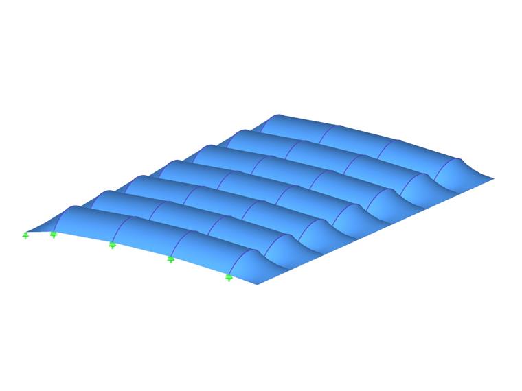
The roof includes a double curvature textile cover supported on a timber arch substructure. The roof membrane has a separate module for each panel. The fabric is inserted into aluminum sections which are further attached to timber rafters. Tensioning is carried out by the metallic tensioning arches and a cable at one end. The continuous membranes at the facade are fixed at the perimeter in plate-shaped grooved sections, and the canvas is fixed to the intermediate columns to prevent displacement.Project Location
Rue du StadeKeywords
ACS Production Roof Membrane Form-finding:
Write Comment...
Write Comment...
Contact Us
Do you have any further questions or need advice? Contact us via phone, email, chat or forum or find suggested solutions and useful tips on our FAQ page, available 24/7.

New
Evaluating and Documenting Steel Joints Analysis Results in RFEM 6
With the RFEM 6 add-on Steel Joints, you can analyze steel connections by using an FE model. This article demonstrates how to evaluate and document the steel joints analysis results.

New
Application of Connections to the Structure | Steel Joints
- The proposed connection can be applied to all selected nodes in the structure
- The location of the connection can be defined using the "Main" tab of the Add-on dialog box
- The design is performed for all connections in the structure and after the calculation, the results on all connections can be displayed
- The table shows the results for the individual connections, each connection is designed and can be saved separately
- Which Dlubal Software programs are required to calculate membrane and tensile structures?
-
How do I set a release for warping?
- How can I define a warping spring or a warping restraint?
- At which point on a cross-section are the supports and loads assumed for the calculation with warping torsion?
- The limit stress is activated, but my stress ratio is “non-designable” in the Stress-Strain Analysis add-on. What could be the reason?
- How can I define a warping spring or a warping restraint?