Answer:
It is correct that the rib members defined in the model are not taken into account when calculating the realistic deformations in cracked state.
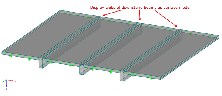
However, you can solve this problem if you do not model the downstand beams as rib members, but replace them with a surface model. Thus, the entire slab can be modeled as a surface structure and designed with RF‑CONCRETE NL in RF‑CONCRETE Surfaces.