Answer:
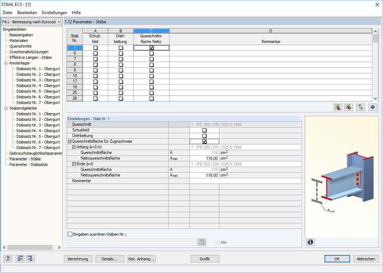
In Window 1.12 "Parameters – Members" and Window 1.13 "Parameters – Sets of Members", you can define the cross-sectional areas for tension design checks according to EN 1993‑1‑1 (see the image).
Sign up for the Dlubal Extranet to get most of the software and have exclusive access to your personal data.
Sign up for the Dlubal Extranet to get most of the software and have exclusive access to your personal data.
Sign up for the Dlubal Extranet to get most of the software and have exclusive access to your personal data.
In Window 1.12 "Parameters – Members" and Window 1.13 "Parameters – Sets of Members", you can define the cross-sectional areas for tension design checks according to EN 1993‑1‑1 (see the image).