Answer:
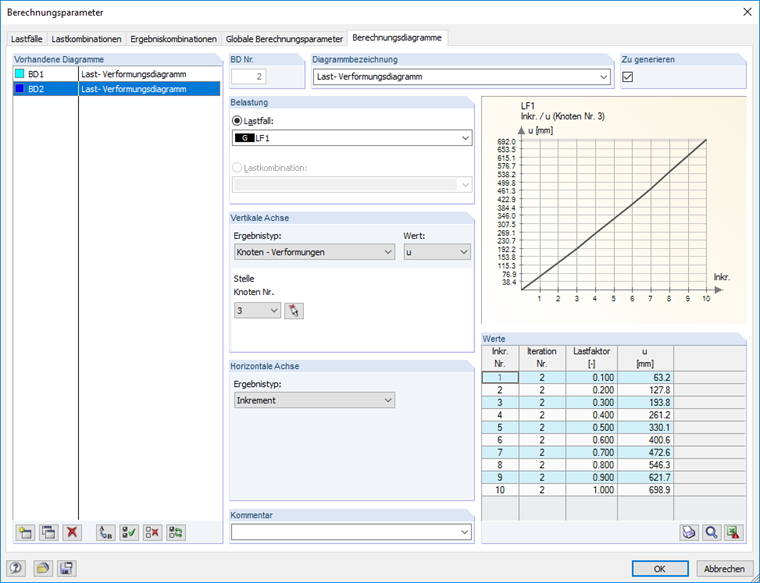
The load-deformation diagram for any node of a model can be defined as a user-defined calculation diagram within the calculation parameters (button or menu "Calculation" → "Calculation Parameters") and displayed with the corresponding results:
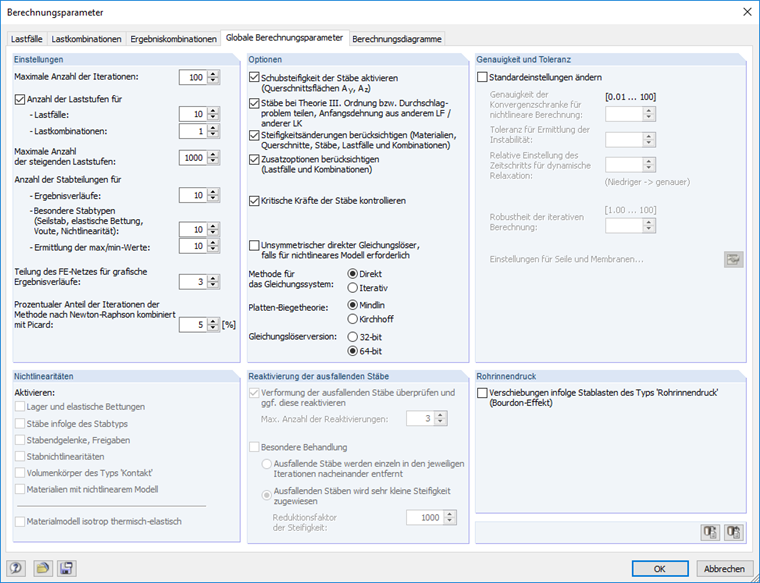
- Setting of the desired load increments within the global calculation parameters
- Definition of a user-defined calculation diagram within the "Calculation Diagrams" tab: Selection of the load case, the corresponding node, and the result types of the horizontal and vertical axis